

As a Mechanical Engineering undergraduate student at California Polytechnic State University, San Luis Obispo, my coursework includes topics such as fluid mechanics, thermodynamics, machine design, and materials science, providing a hands-on foundation in both theoretical principles and practical applications.
Attending Cal Poly in this fashion has given me the unique experience to truly "Learn by Doing." First, the theory behind the application or topic is taught, and then we are given the chance to actually try, fail, and learn for ourselves.
Below is a sampling of some of the experiences I have had as an undergraduate Mechanical Engineering student at Cal Poly!
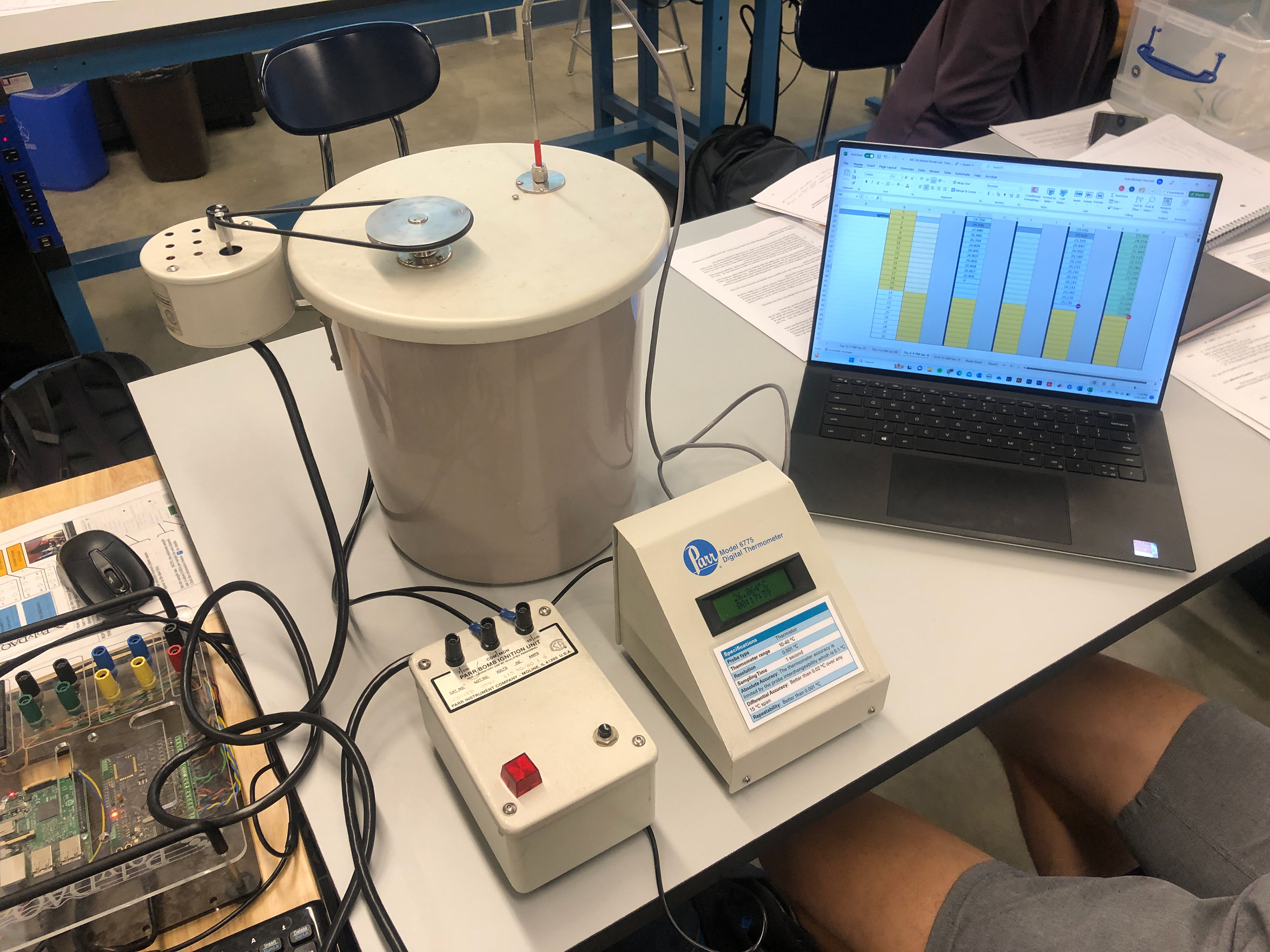
This was in ME-236 "Measurements and Data Analysis" Laboratory class. My lab partner and I were using an apparatus called a Bomb Calorimeter to measure the amount of energy in an energy bar through the process of combustion, where the energy bar was burned in a controlled environment, and the heat released was measured to determine its caloric content.
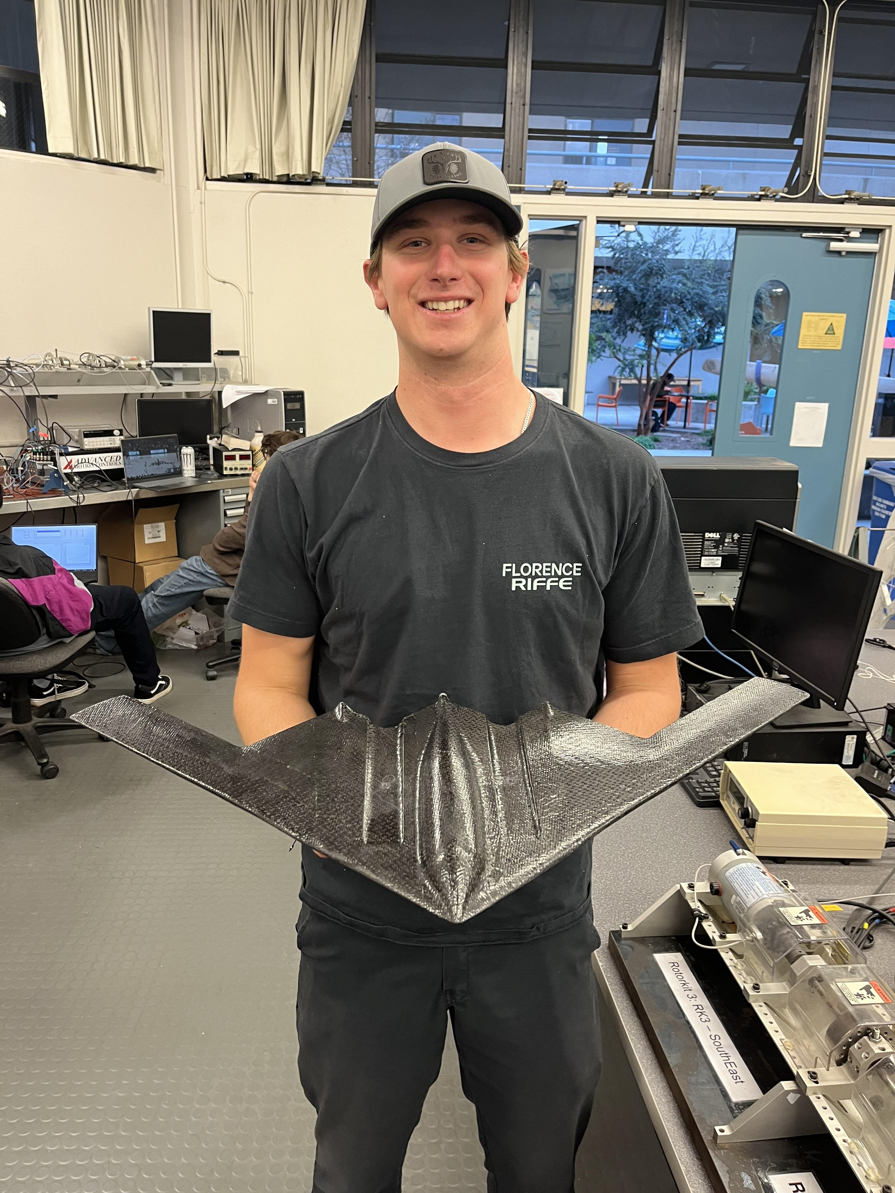
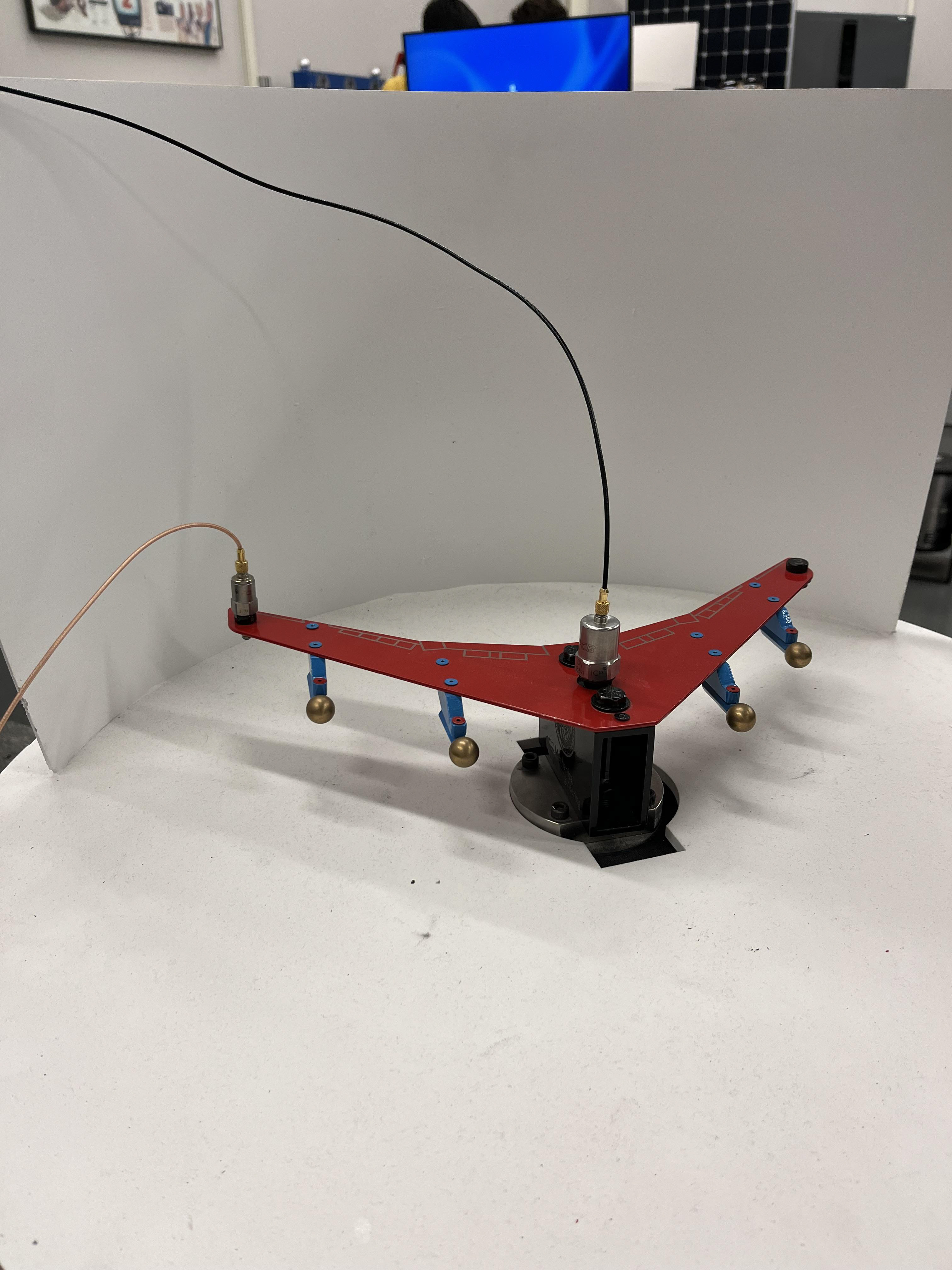
This image is in ME-318 "Mechanical Vibrations" Laboratory class, taught by Dr. Eltahry Elghandour. I am holding a 1/50th scale model of a Northrop Grumman B-2 Bomber "Spirit." In this lab, we were tasked with experimentally determining the mass moment of inertia about the yaw, pitch, and roll axes of the aircraft.
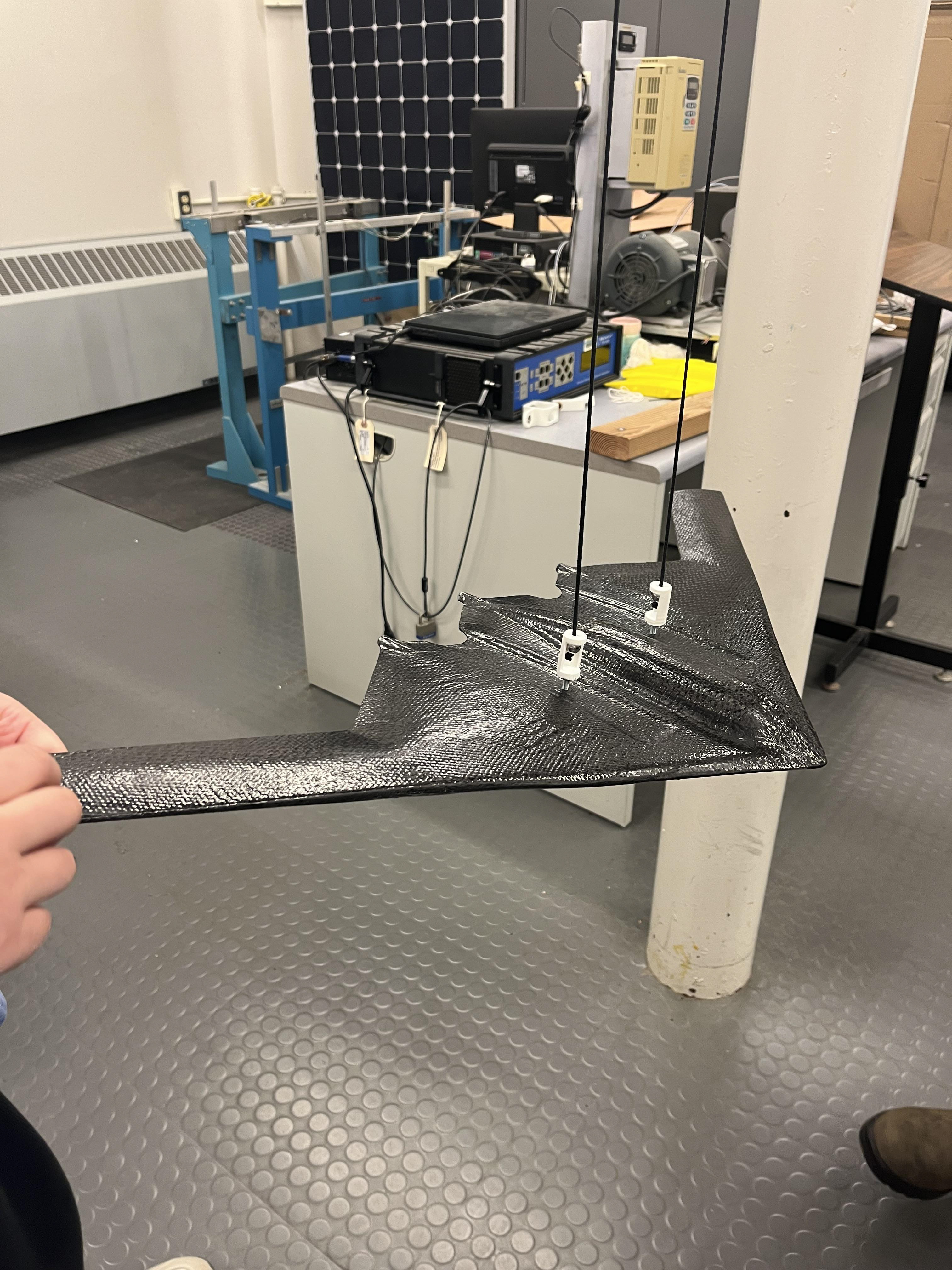
This image is from the same ME-318 "Mechanical Vibrations" Lab, with the B-2 Bomber carbon fiber model aircraft suspended from two points equidistant from the center of mass. This setup was for a torsional test to help determine the mass moment of inertia about the "Yaw" axis of the plane.
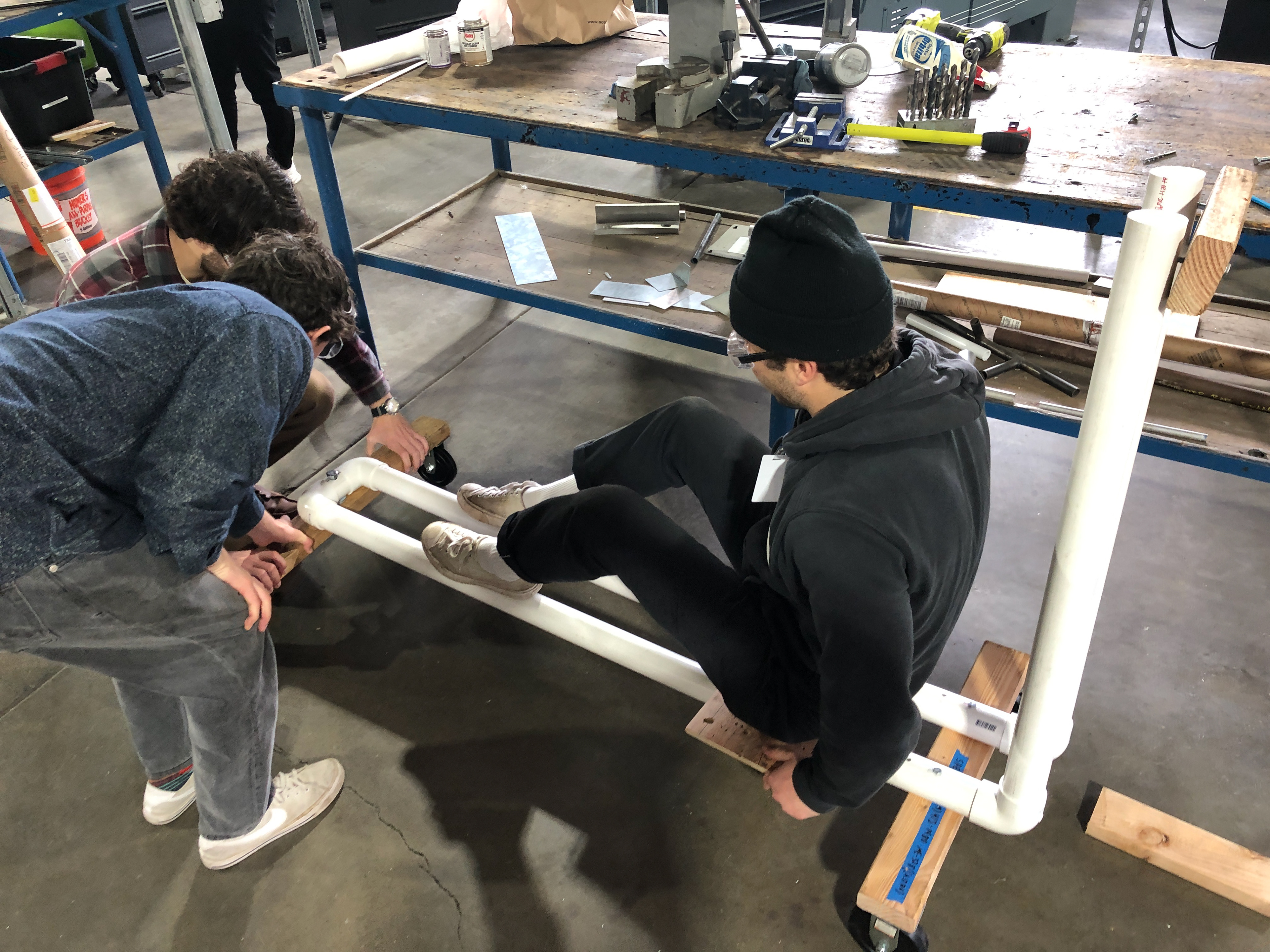
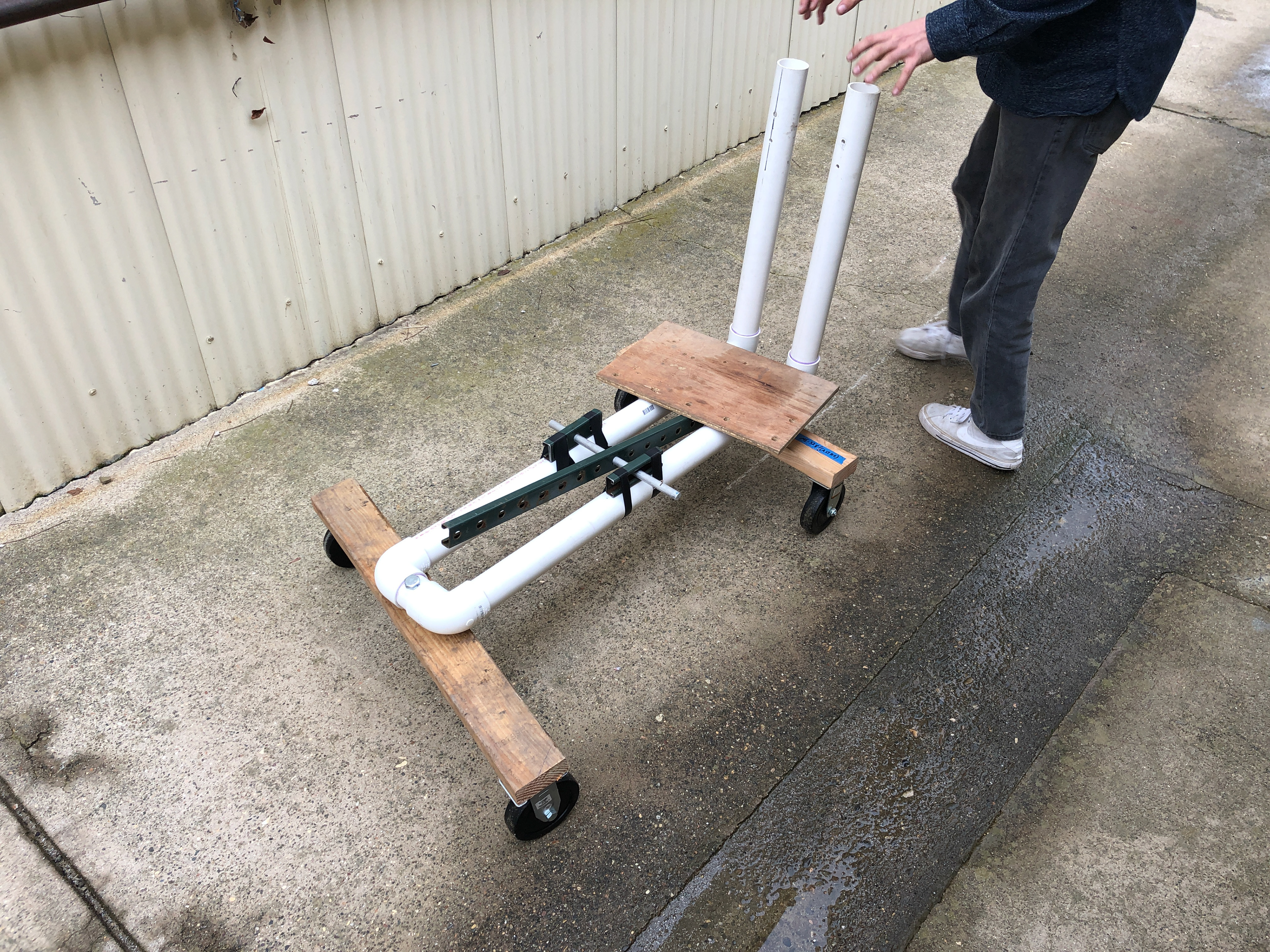
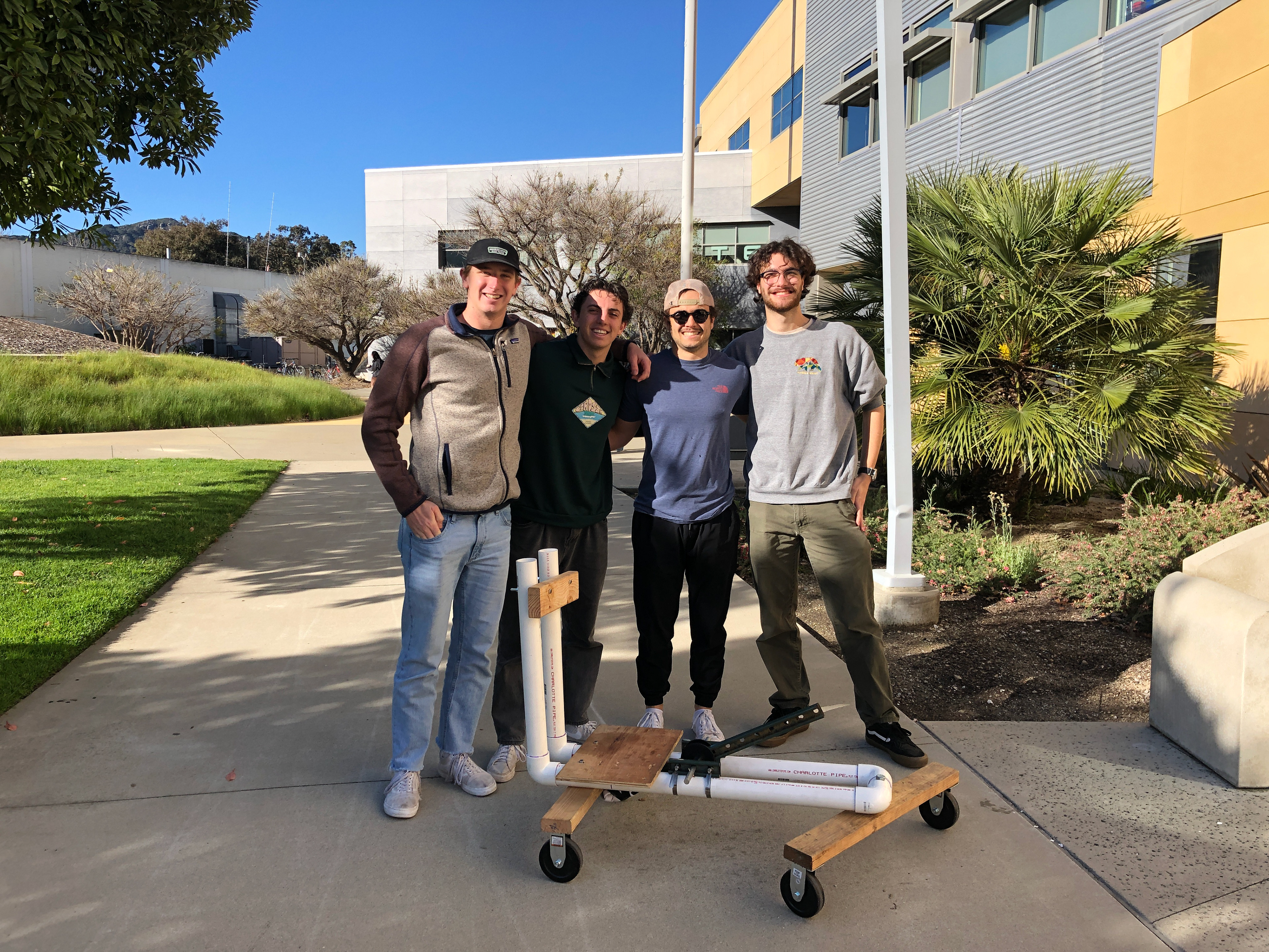
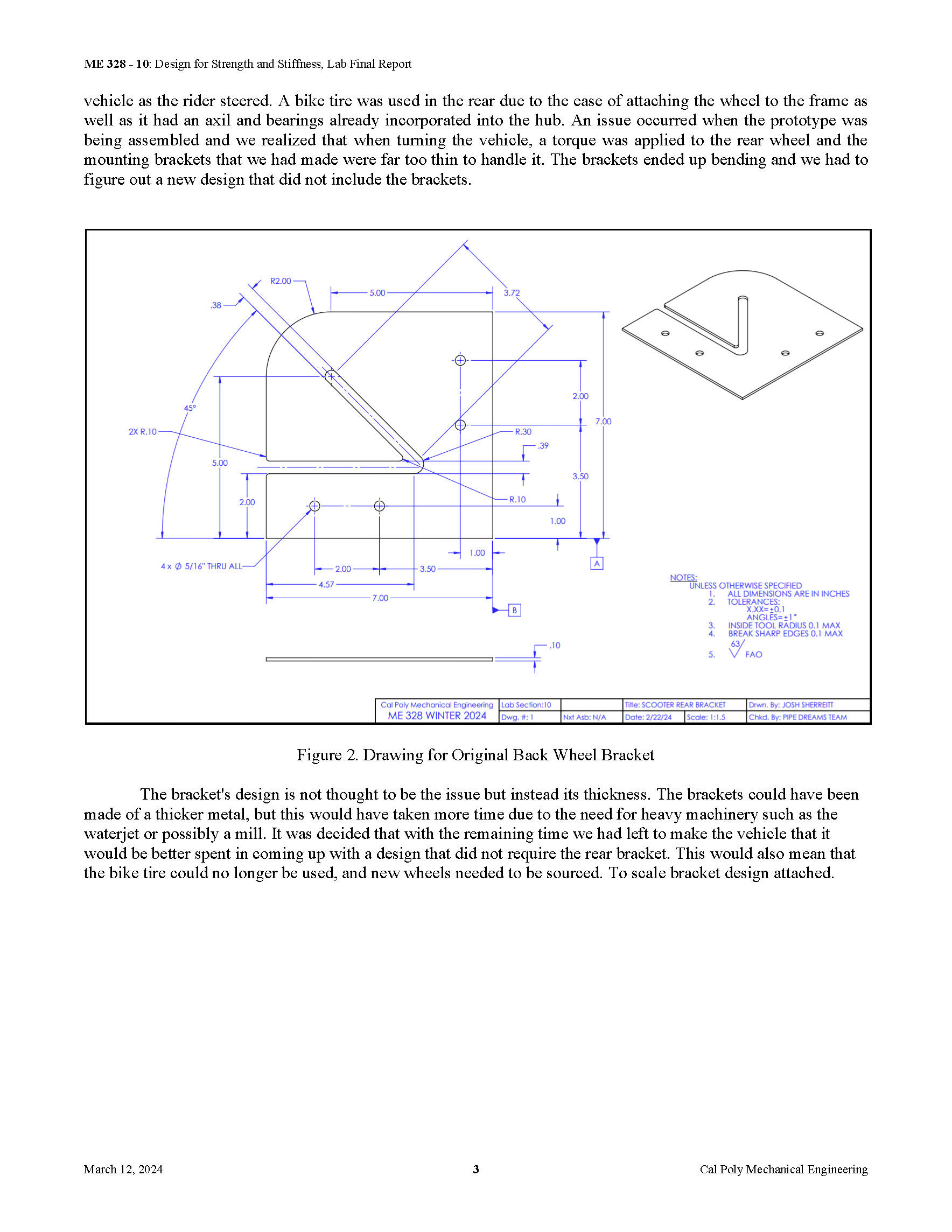
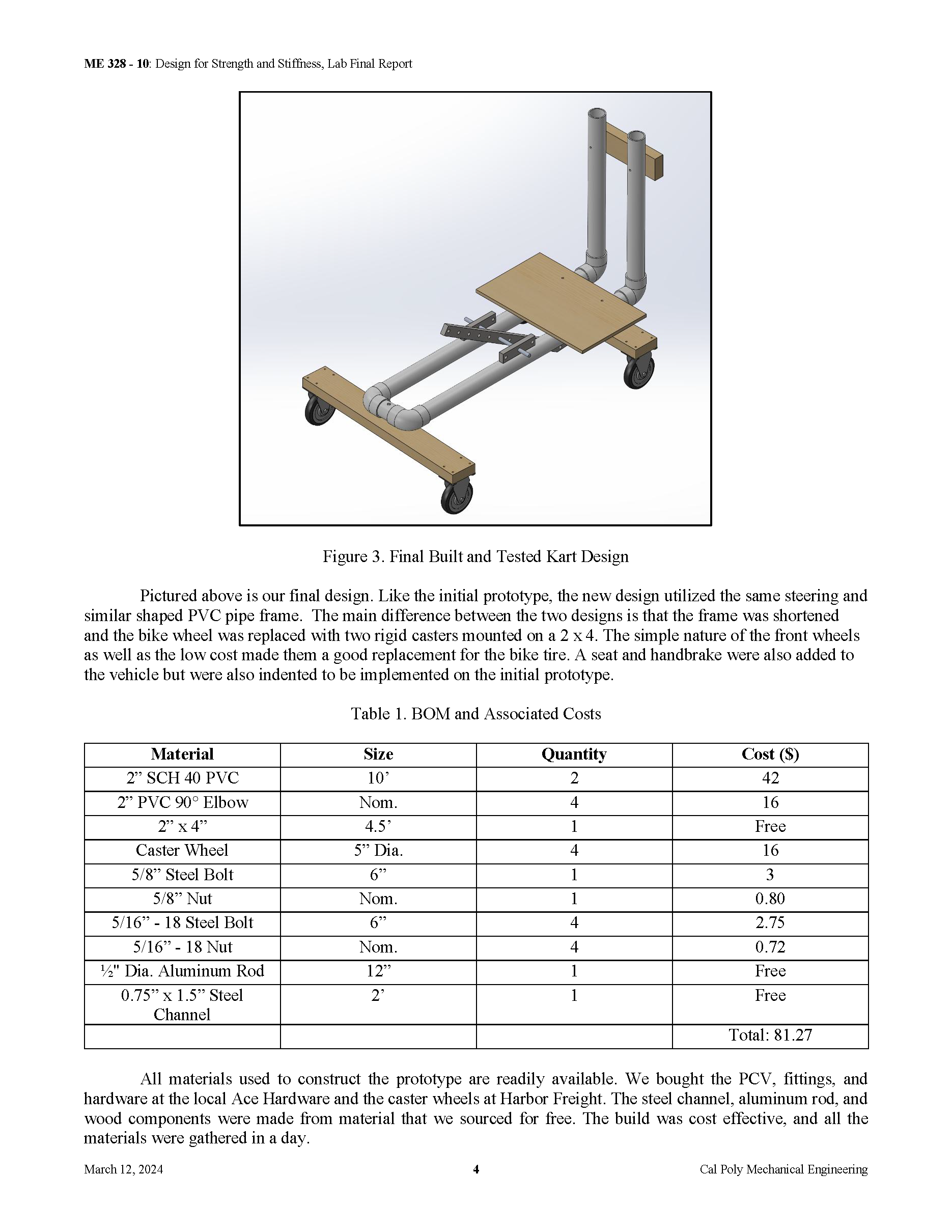
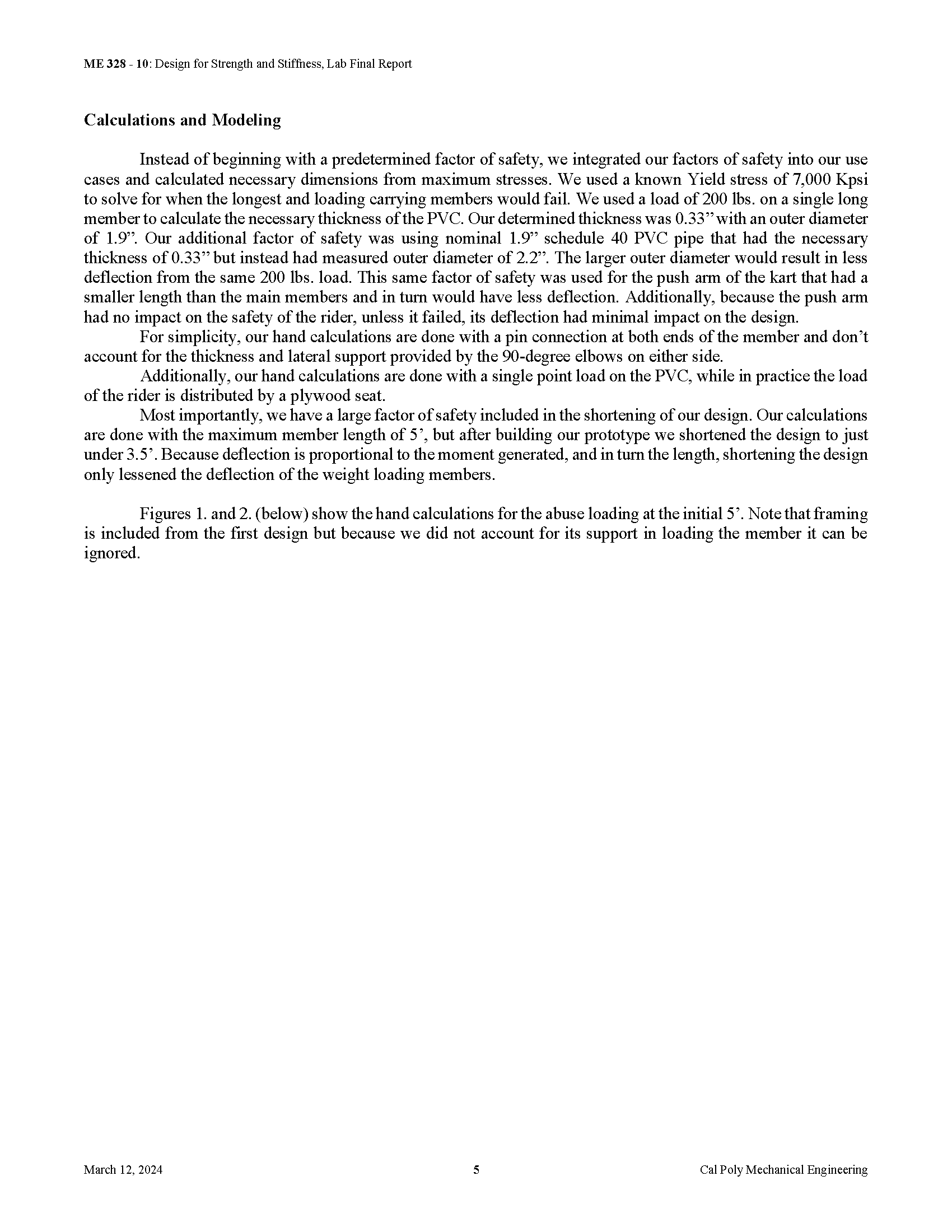
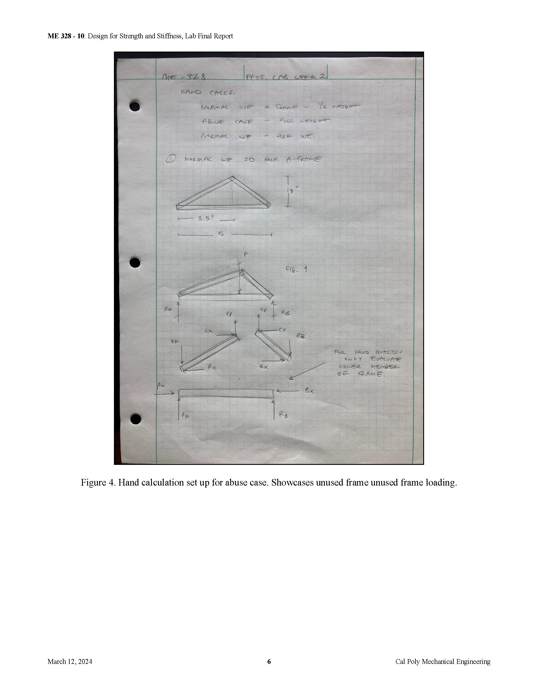
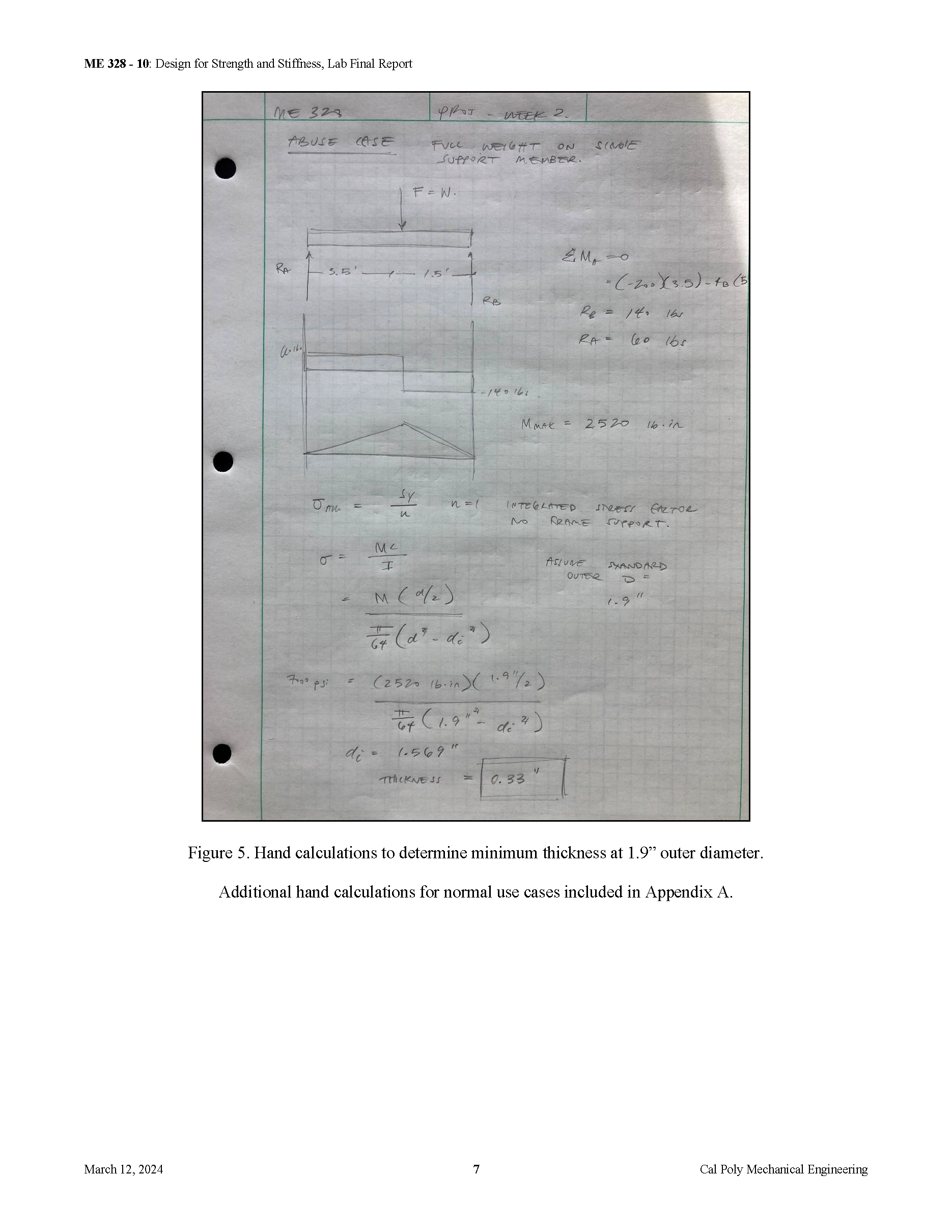
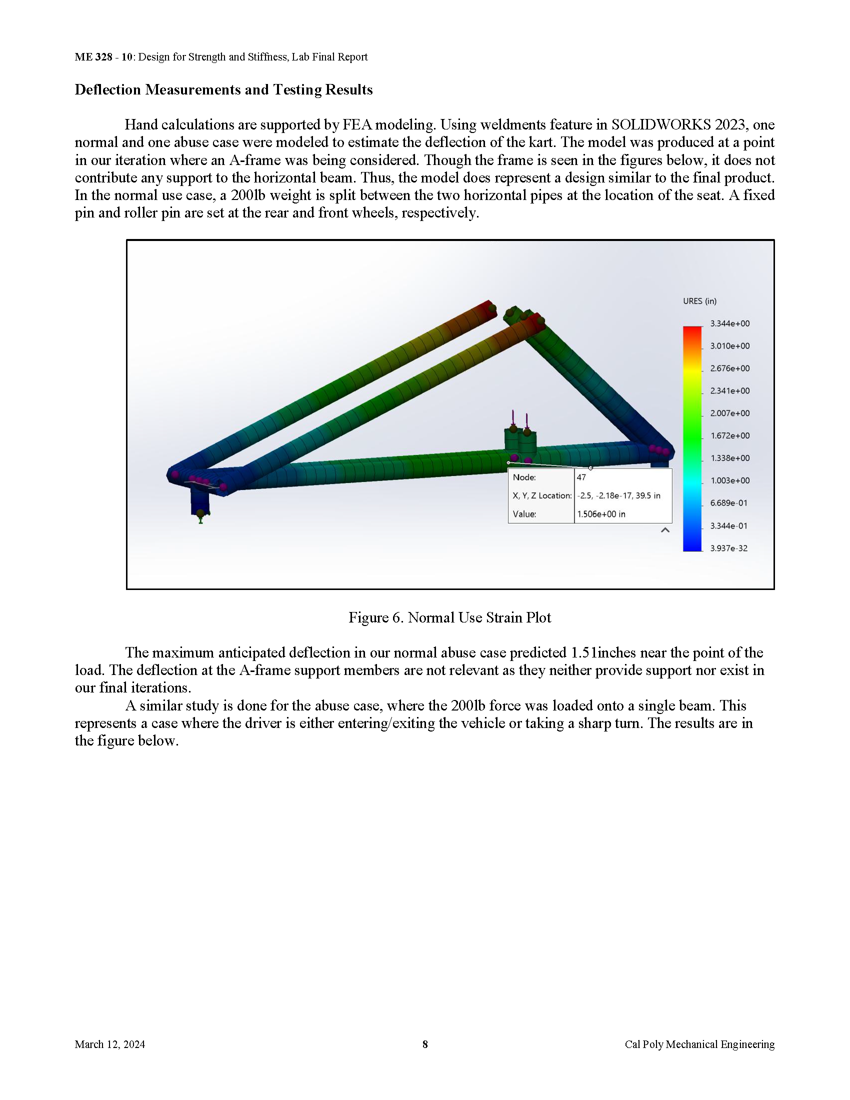
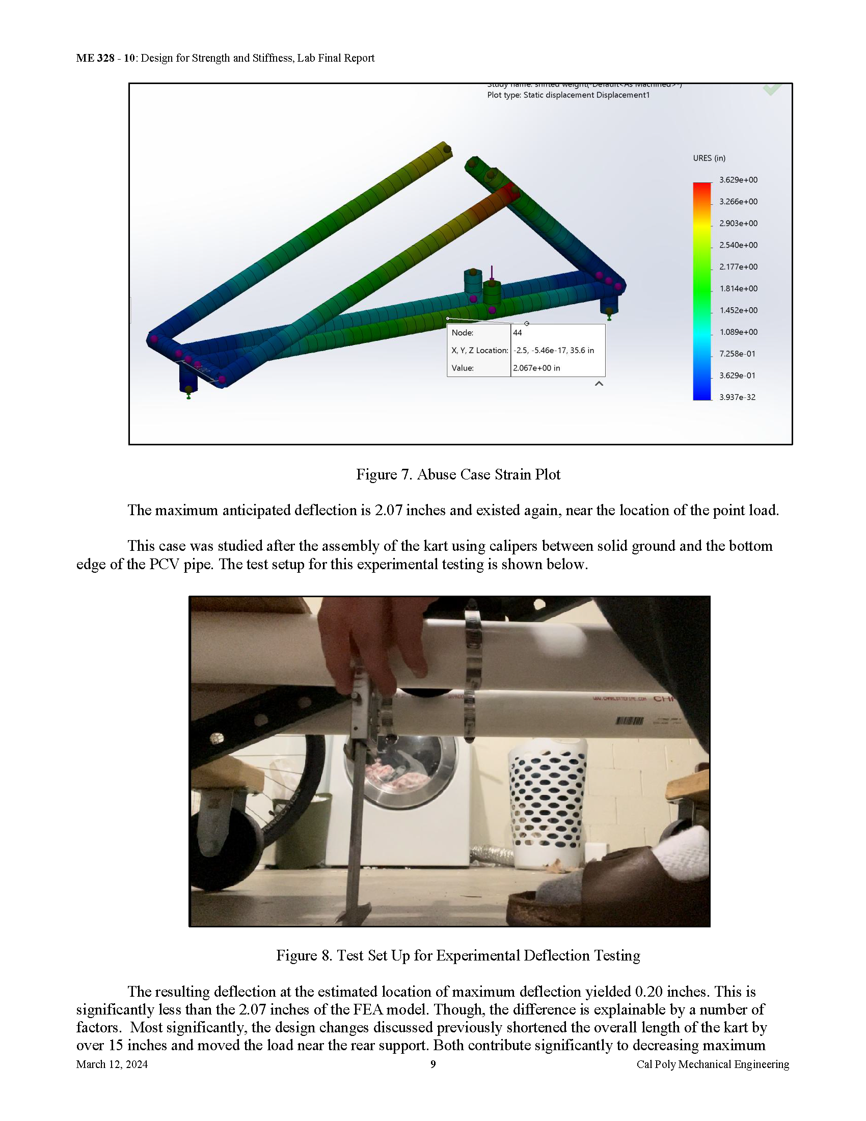
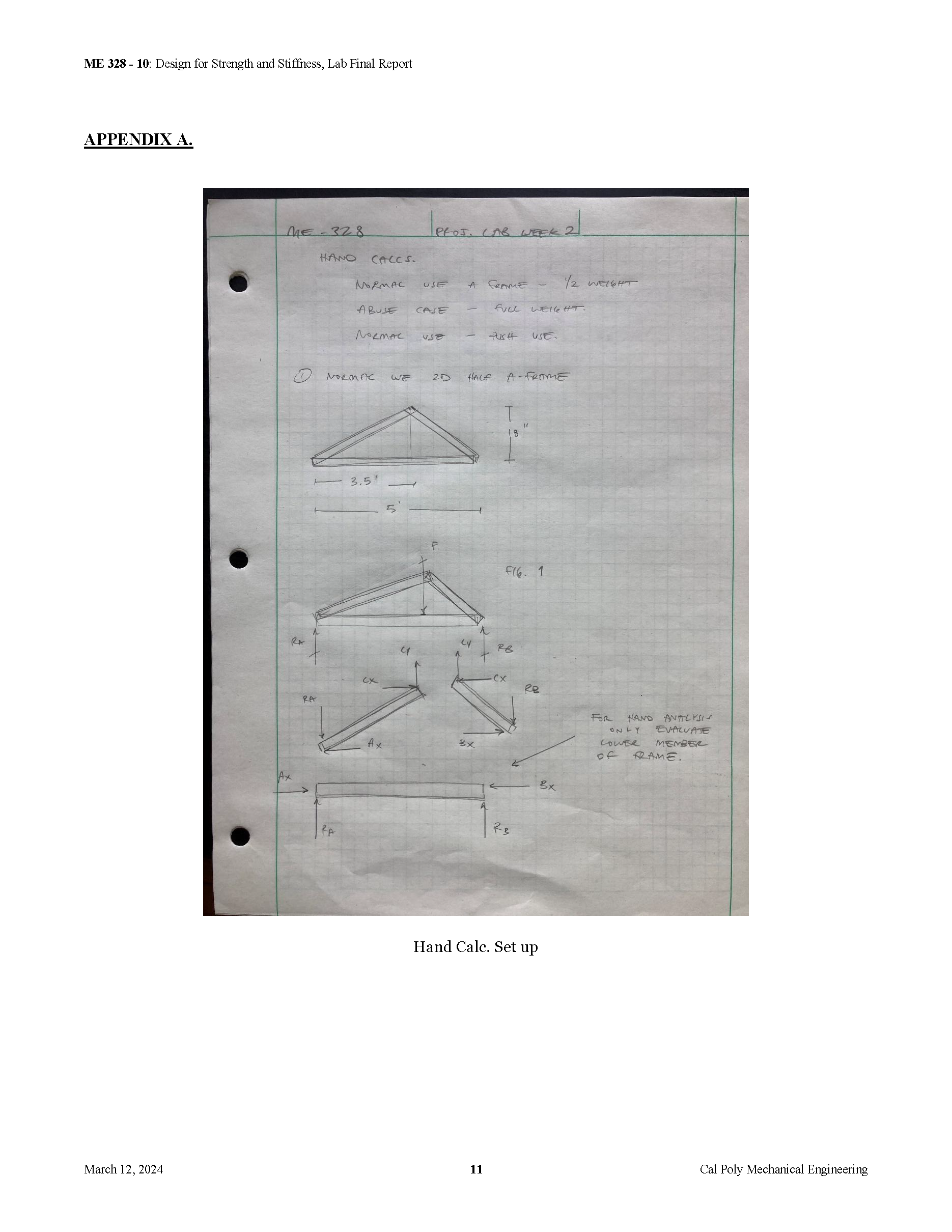
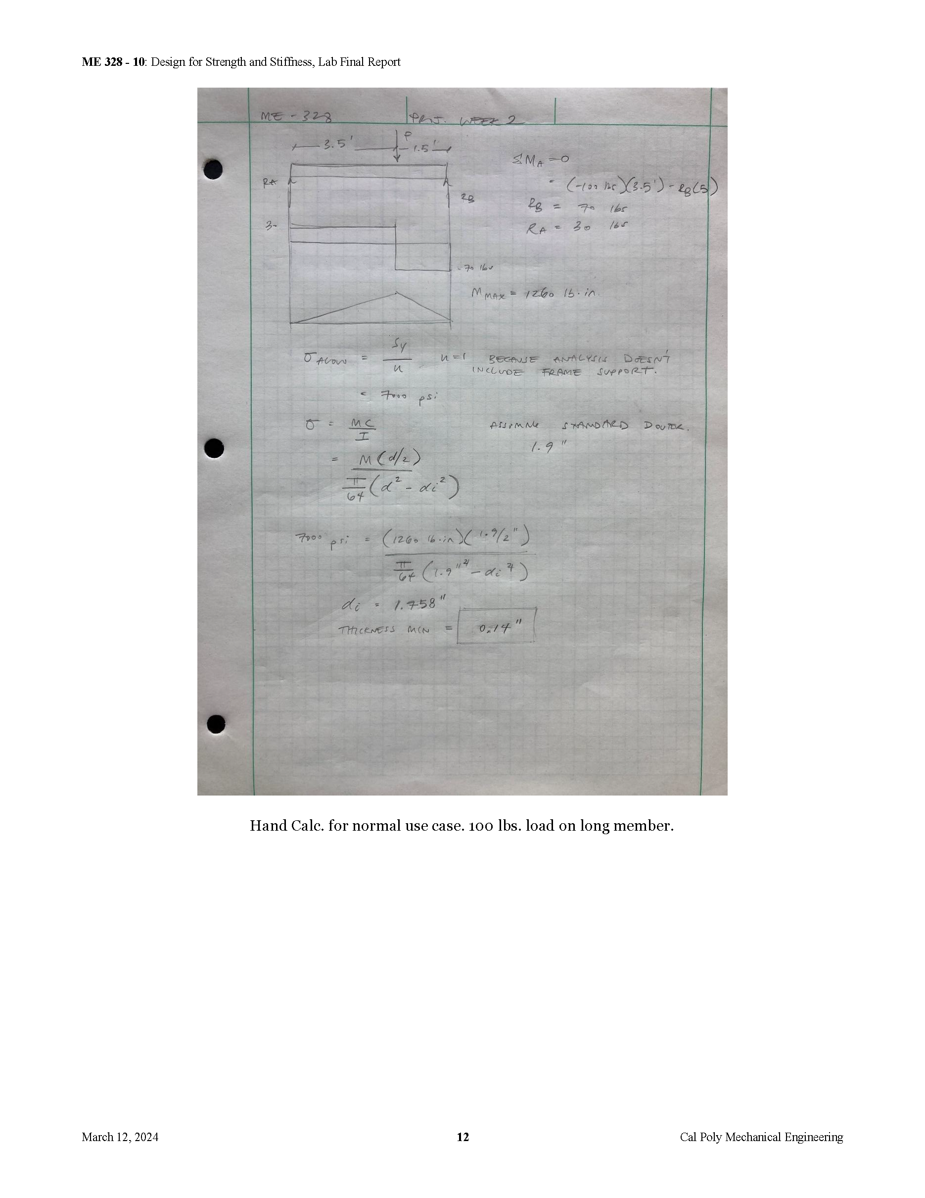
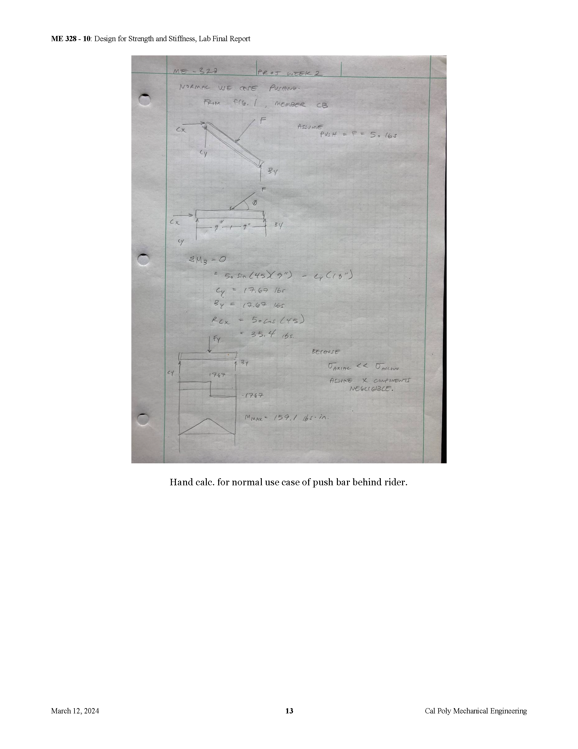
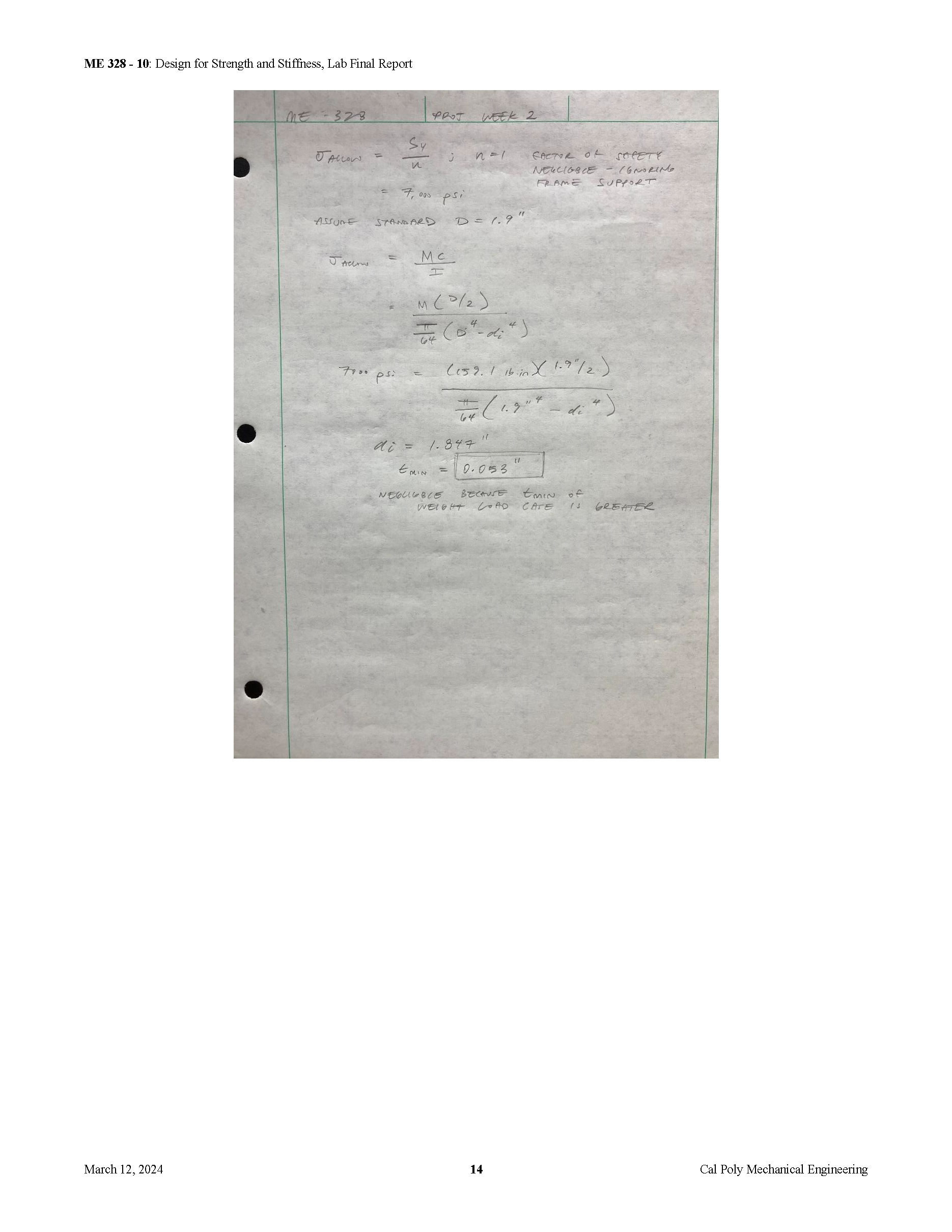
The images above were from ME-328 "Design for Strength and Stiffness I" Laboratory class, taught by Professor Dan Castro. In this lab, my lab mates and I were tasked with designing a scooter using a majority of polyvinyl chloride (PVC pipe).
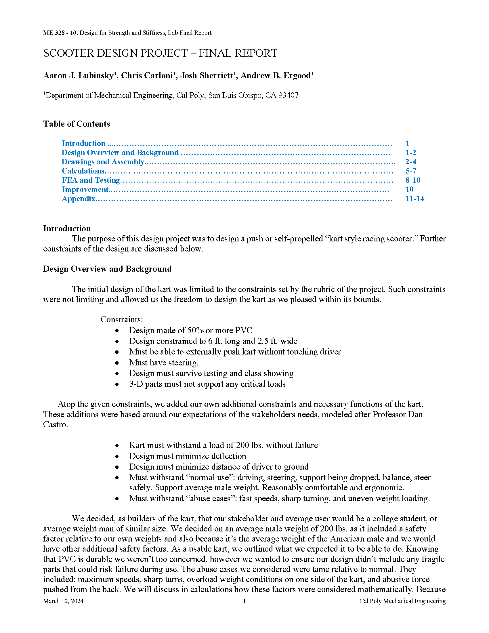
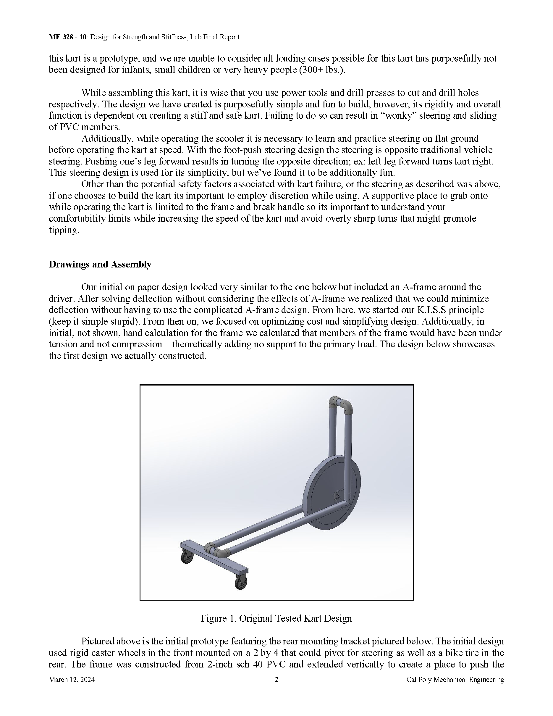
The report, hand calculations, SolidWorks FEA, and following analysis for this Scooter Project in ME-328 "Design for Strength and Stiffness I" Laboratory class is shown on the right. My lab mates (Andrew Ergood, Chris Carloni, and Aaron Lubinski) and I were able to successfully create a scooter meeting the design requirements and prove that our analysis and design were capable of creating a feasible design.
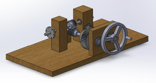
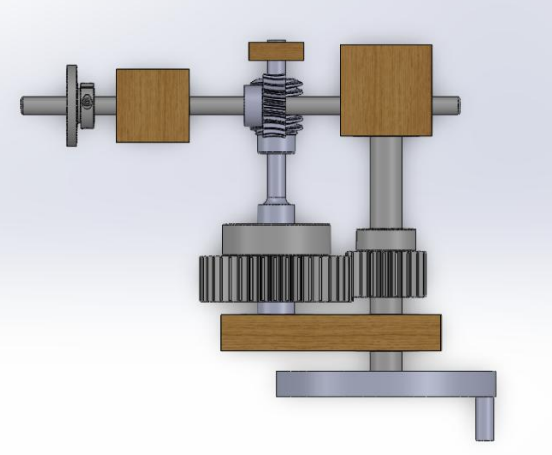
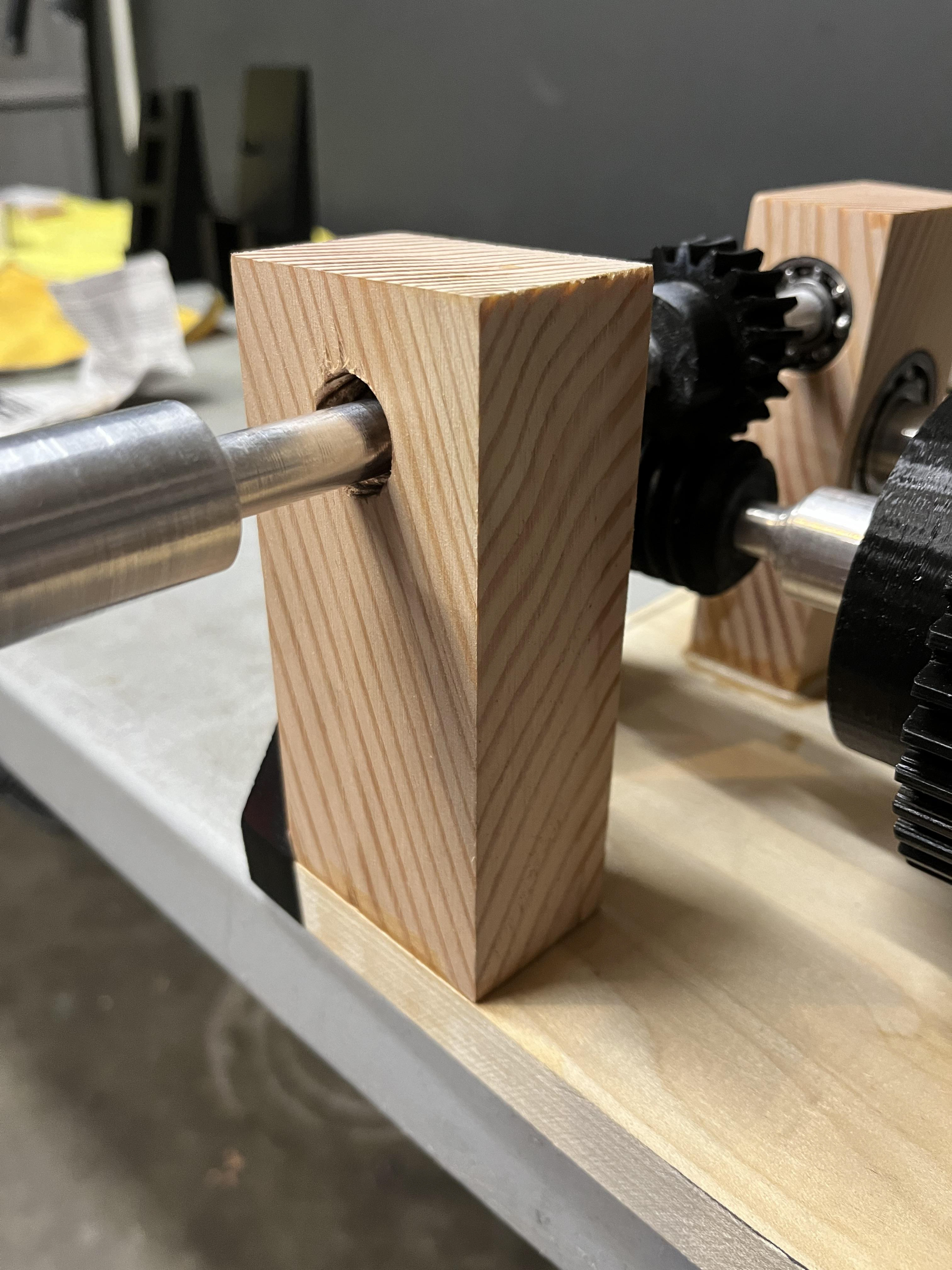
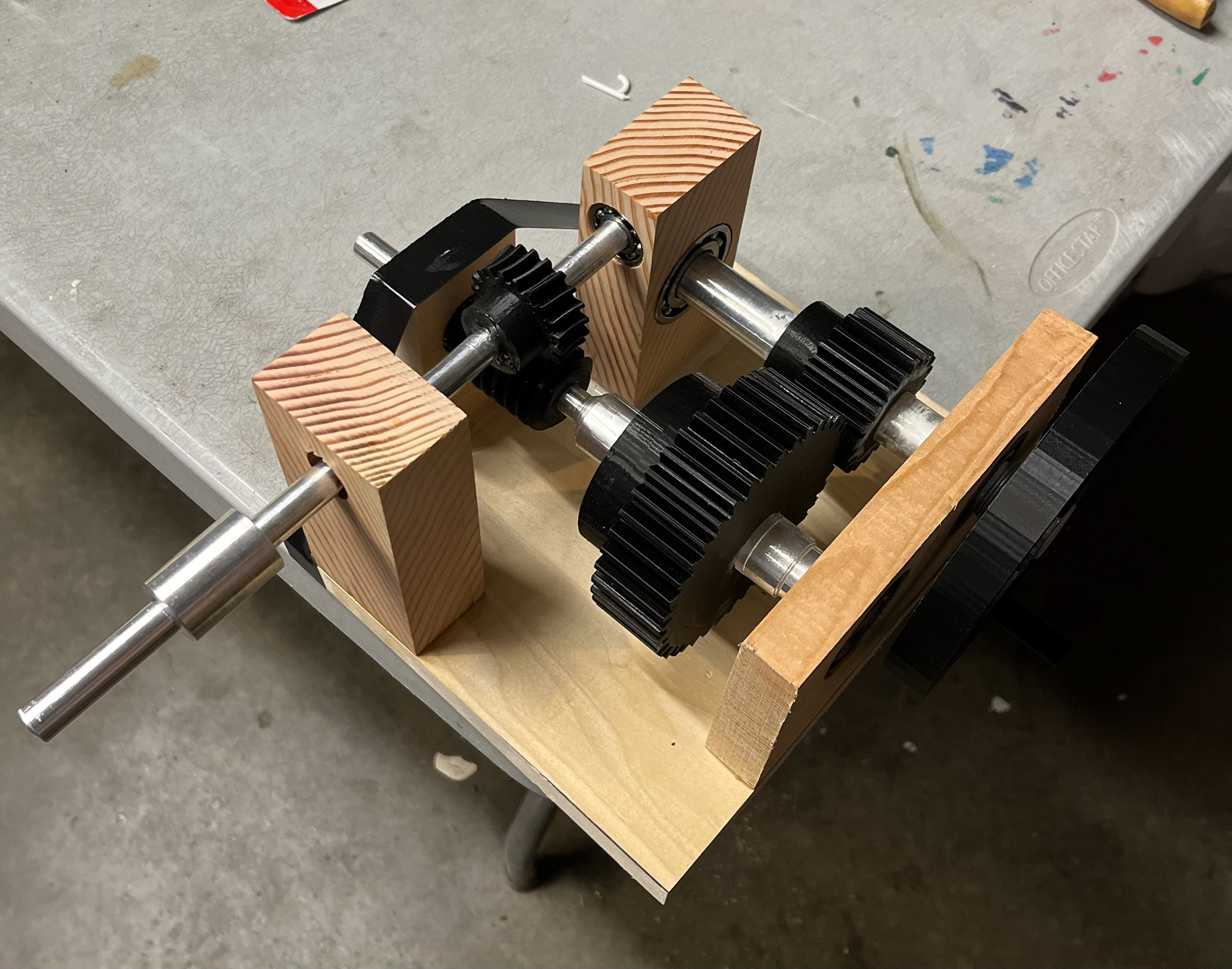
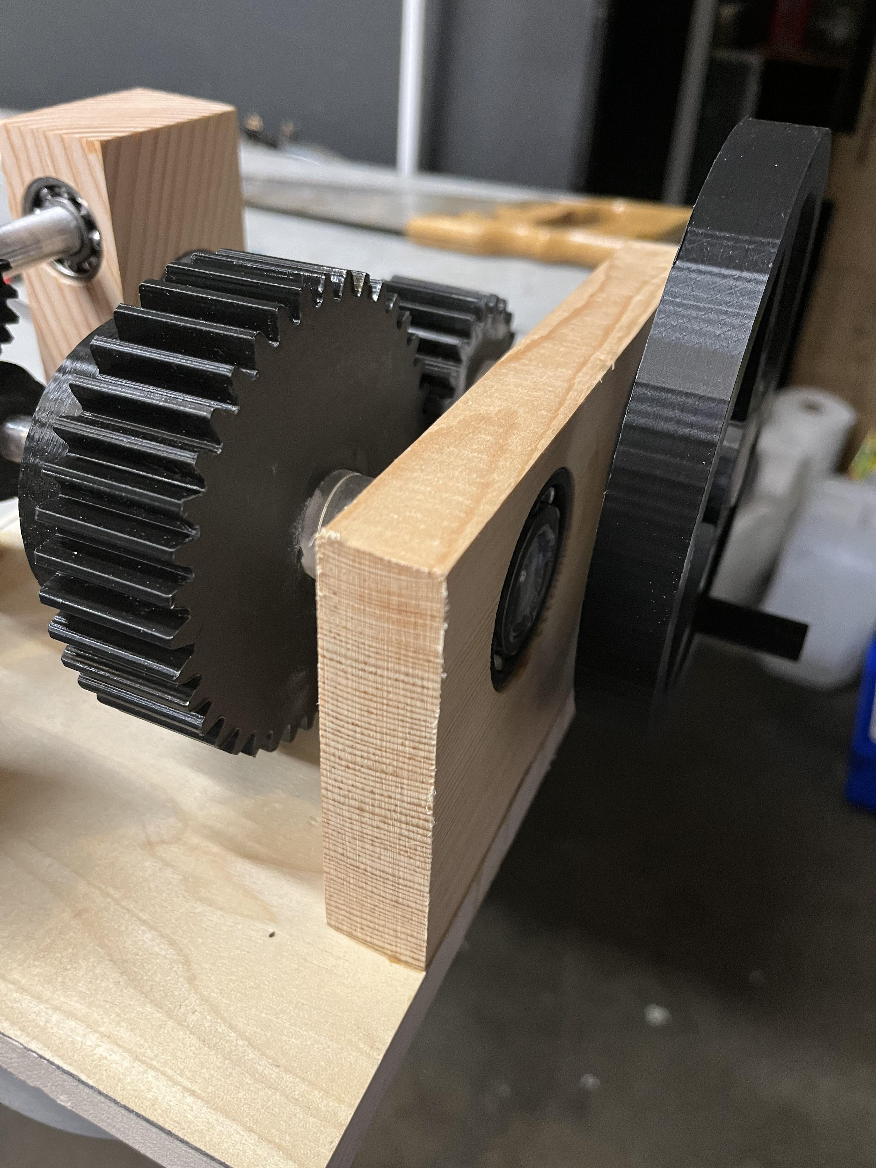
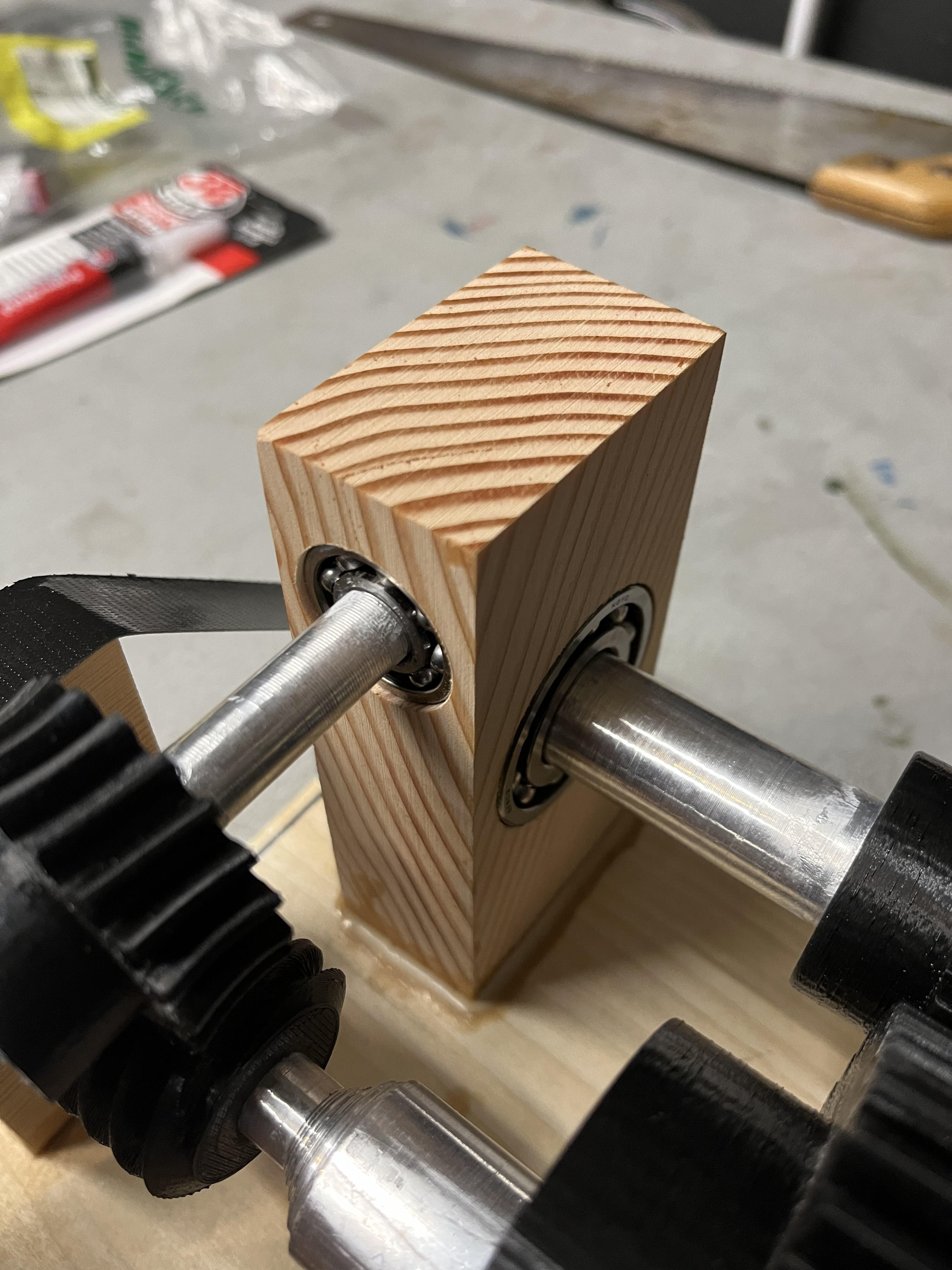
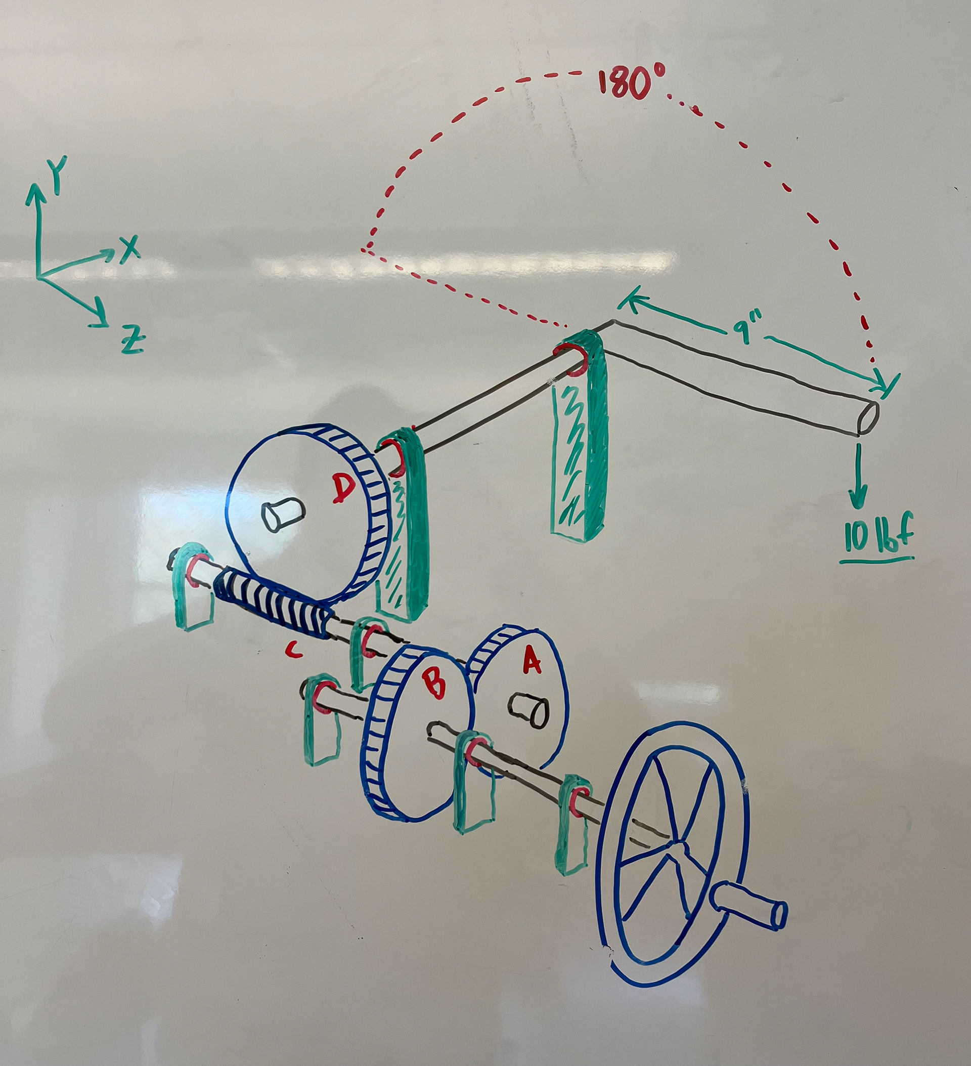
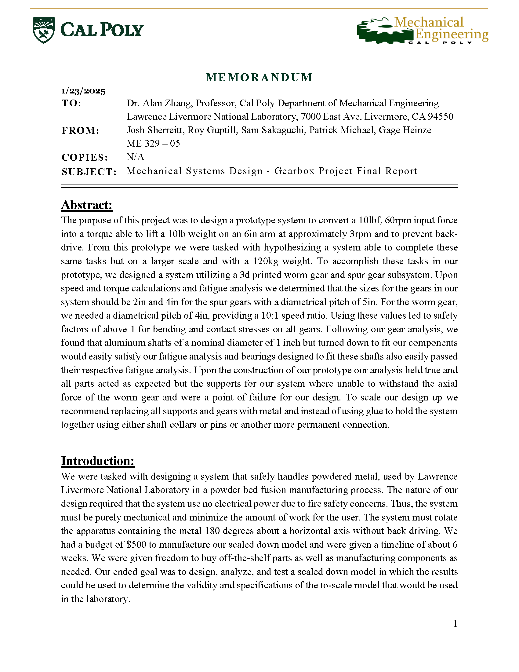
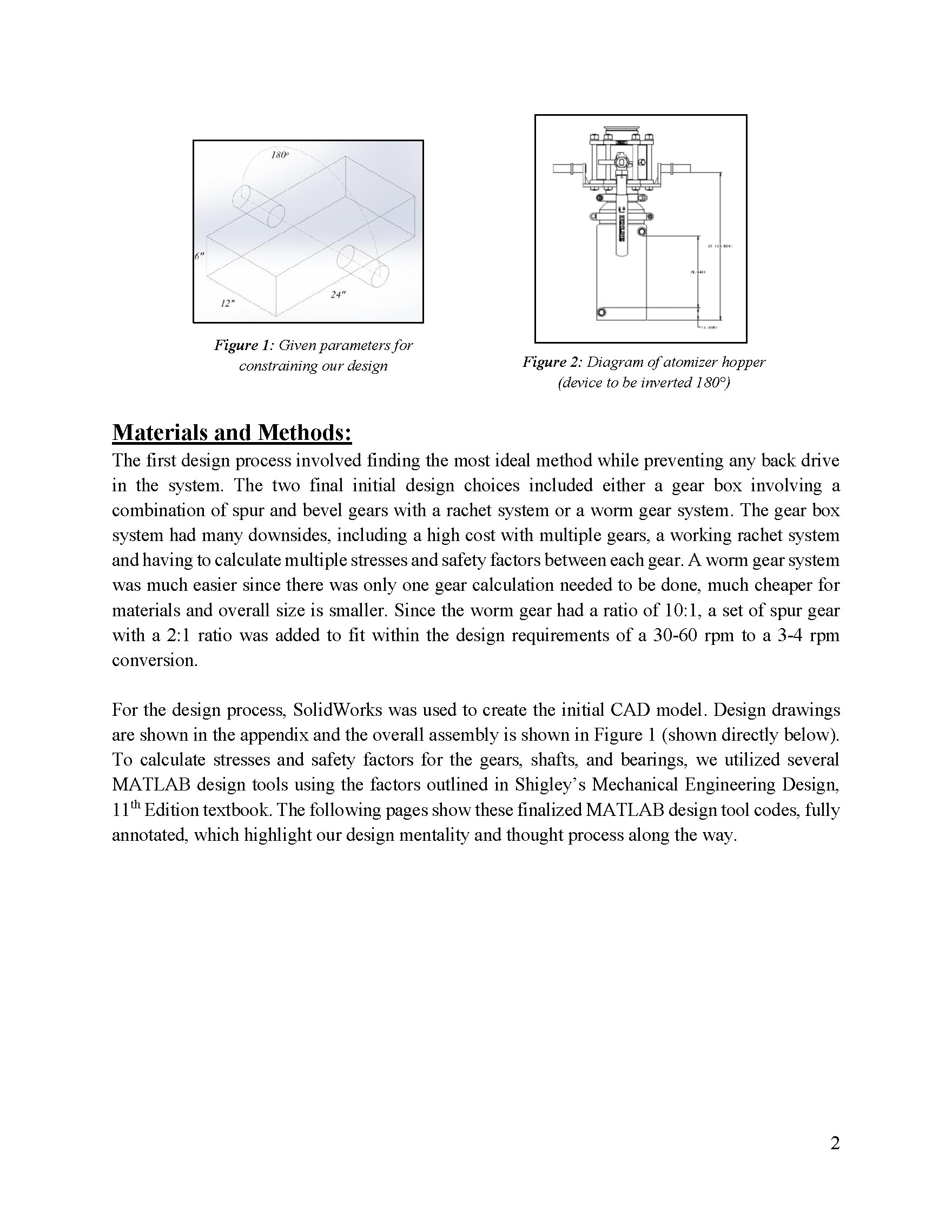
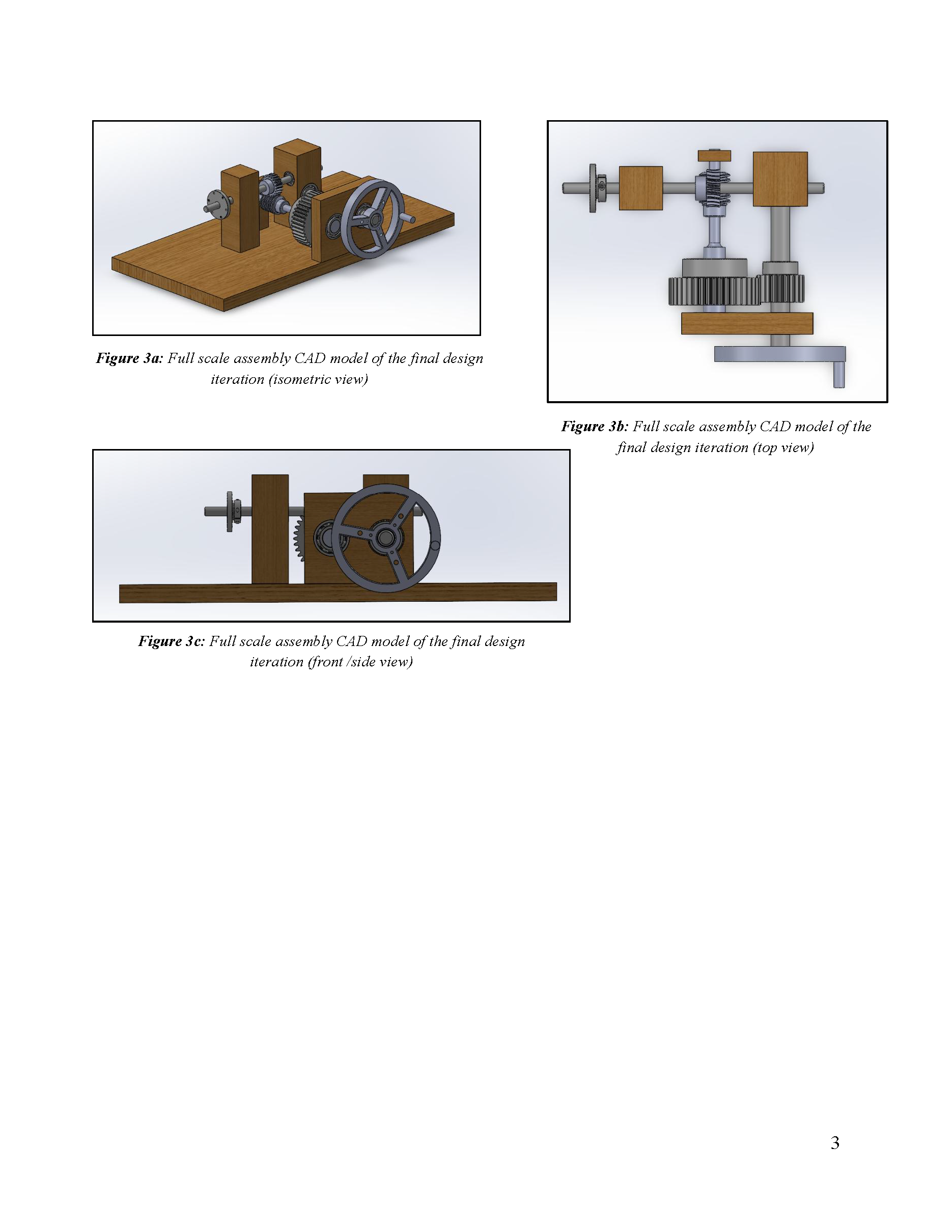
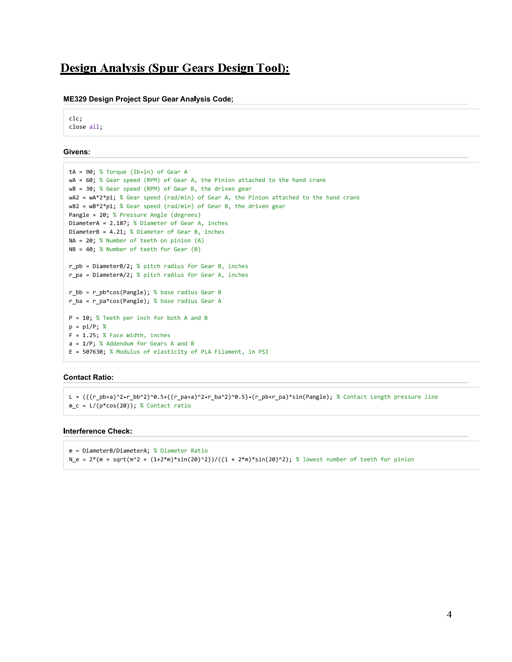
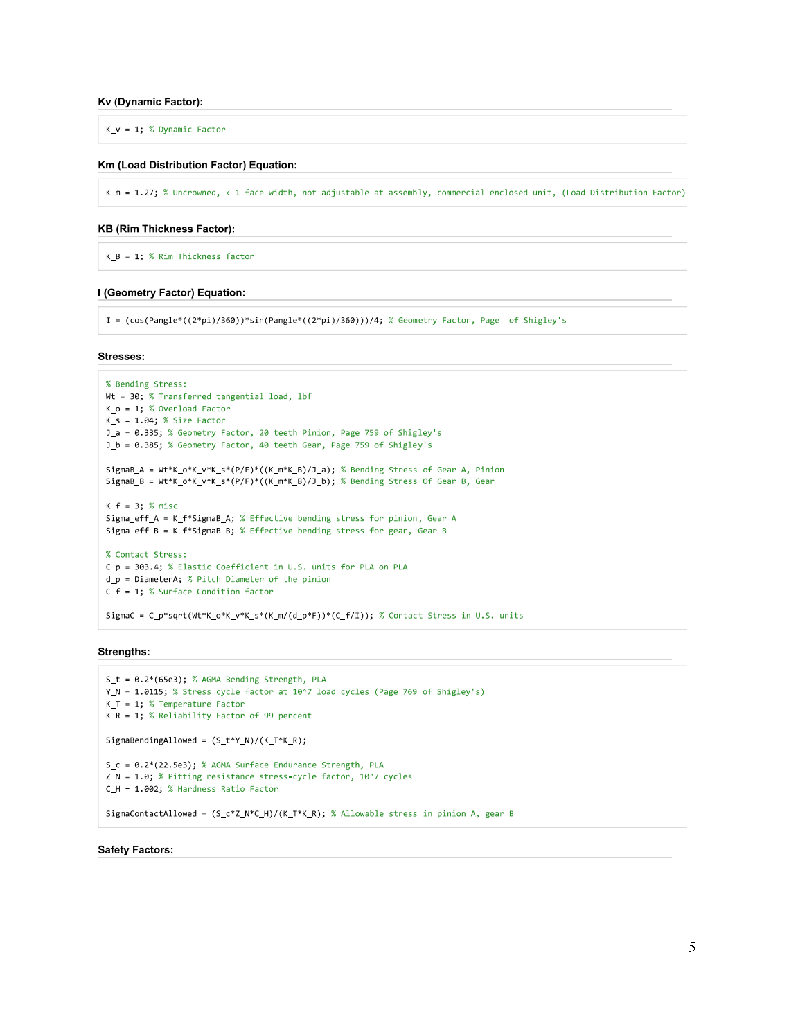
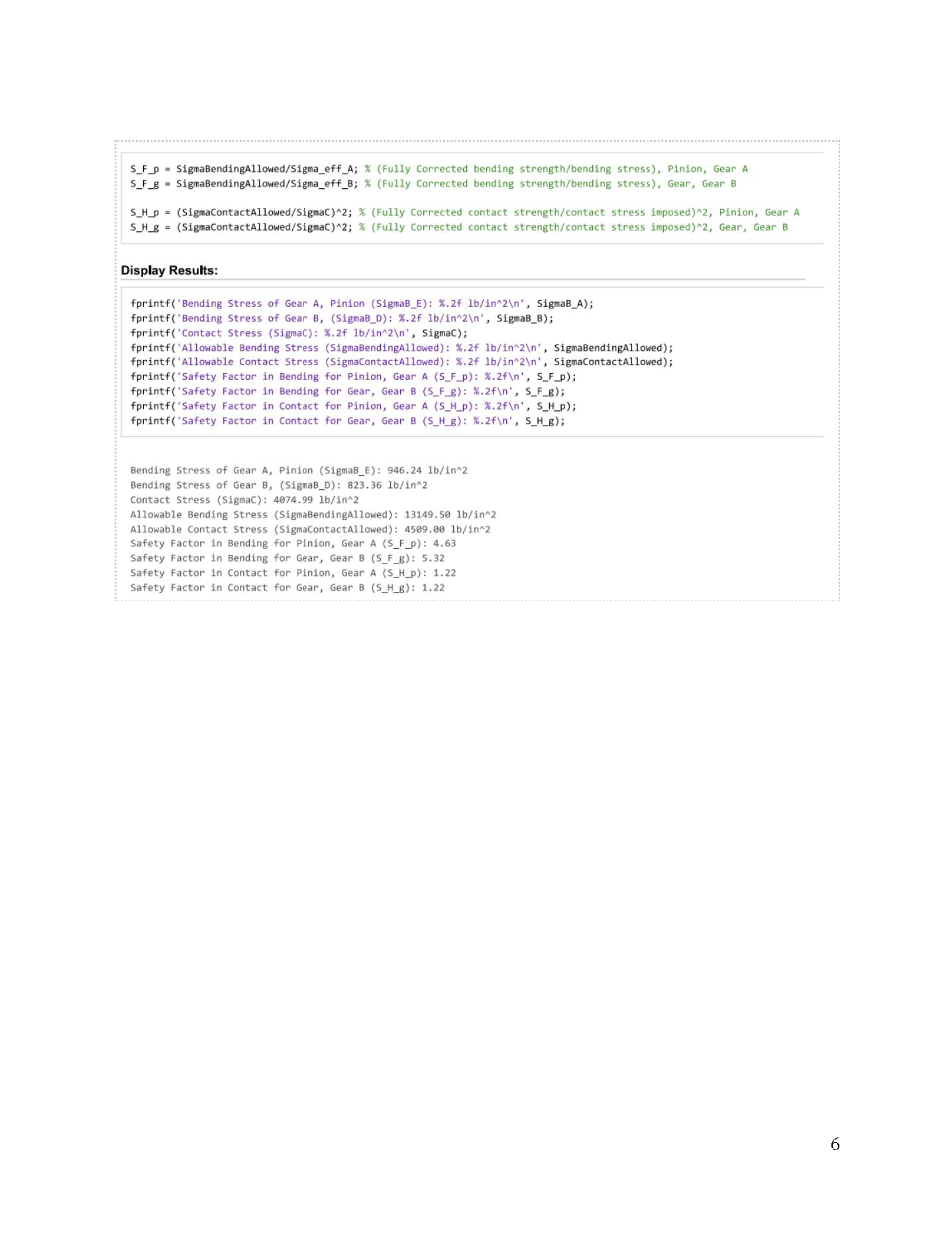
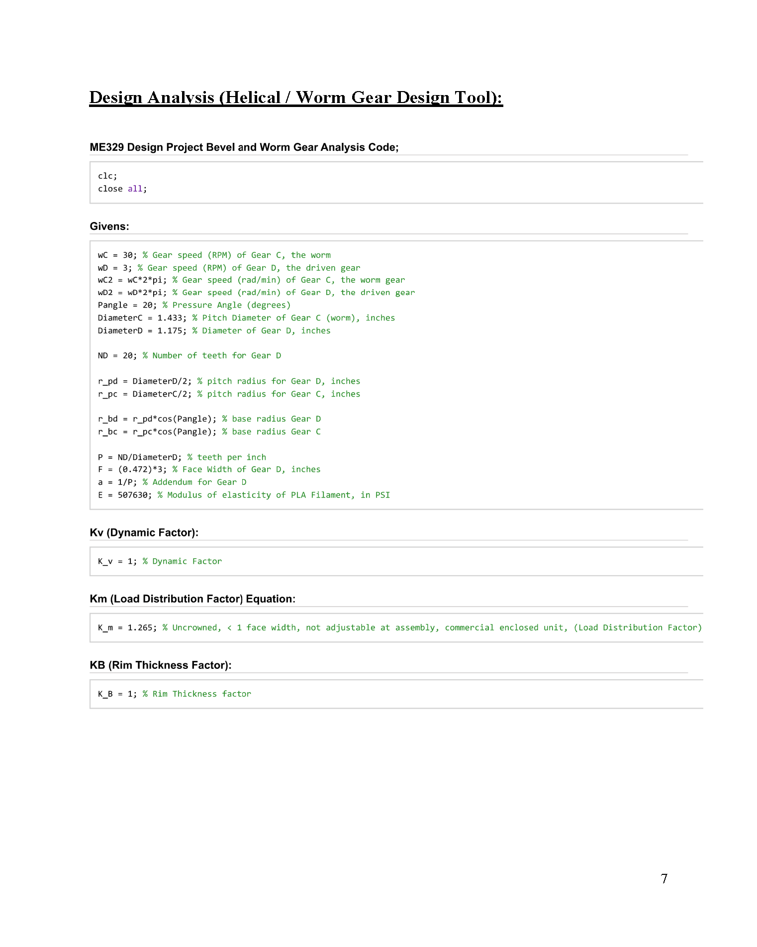
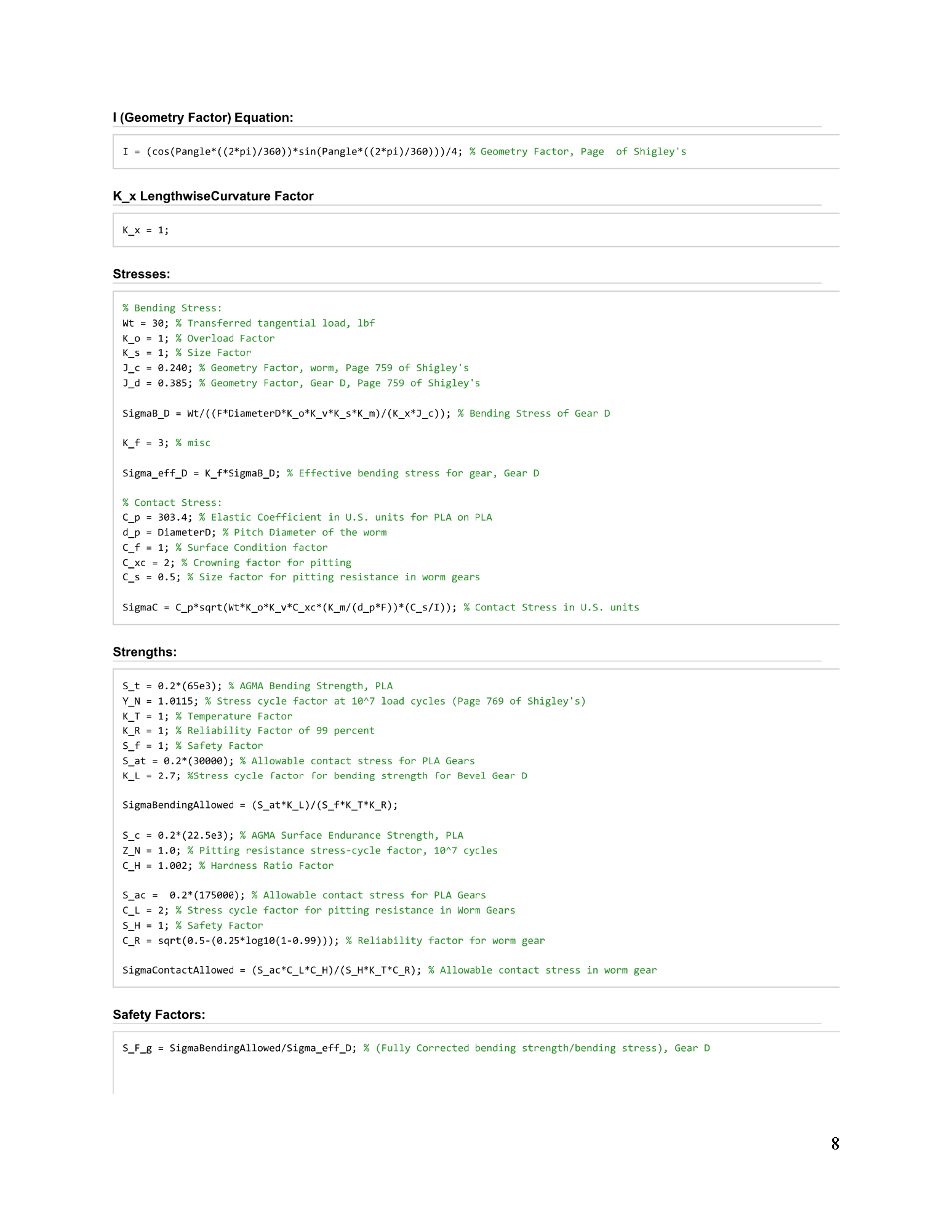
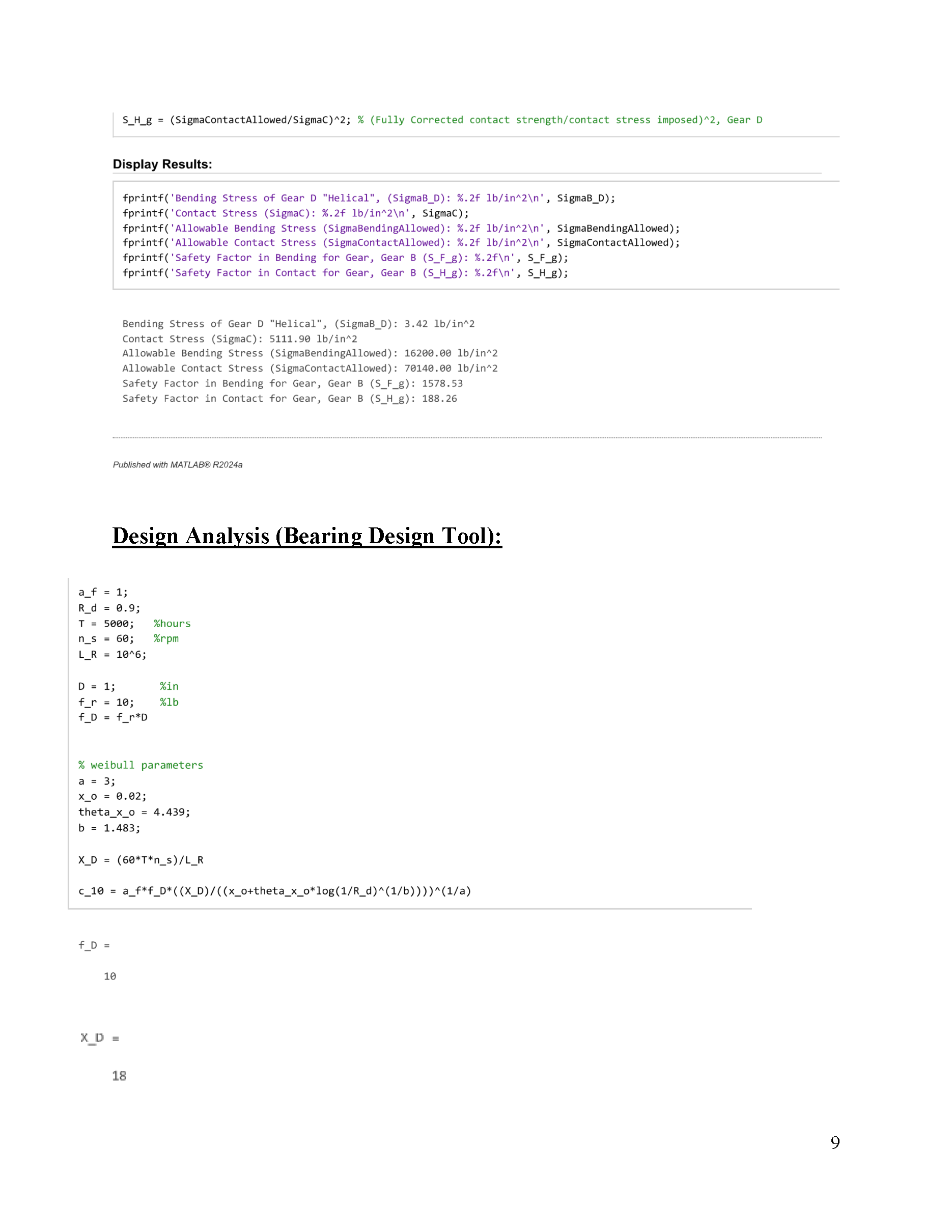
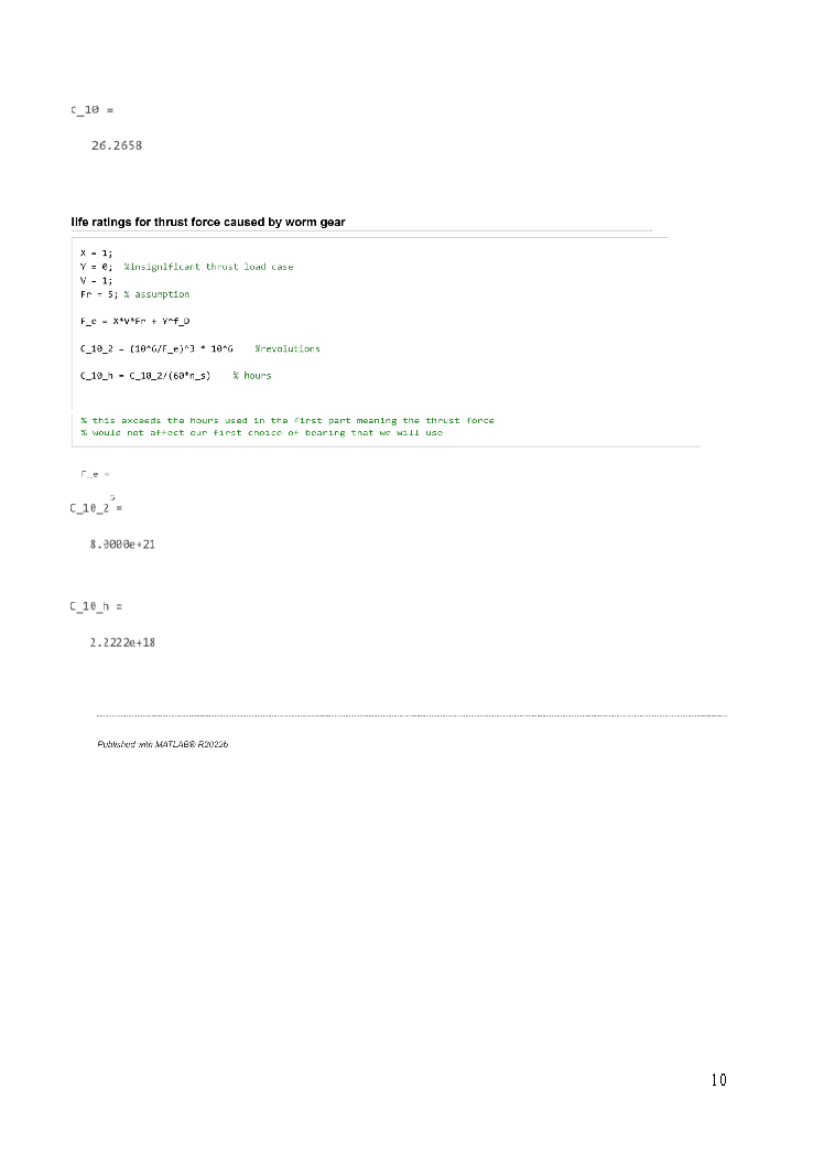
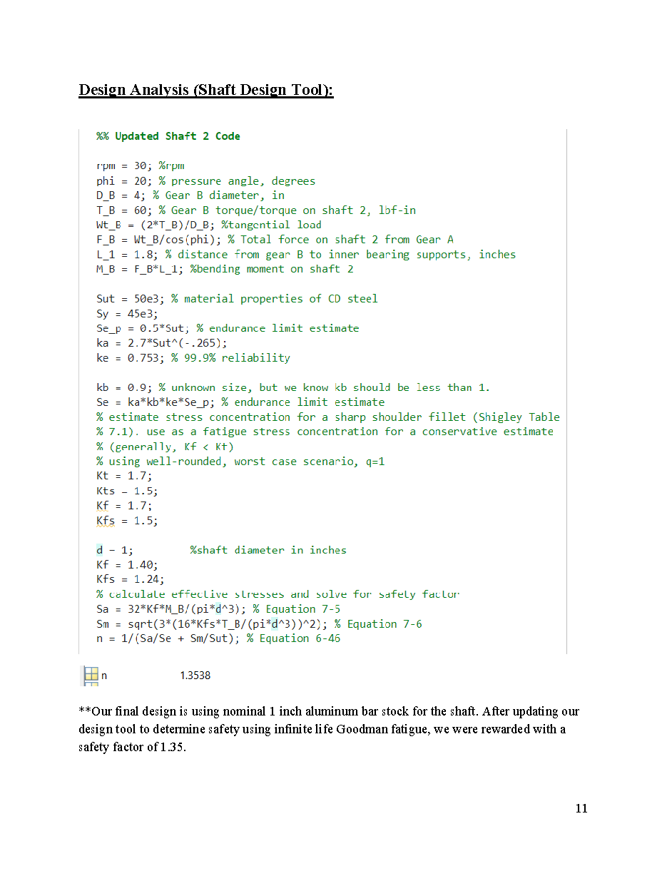
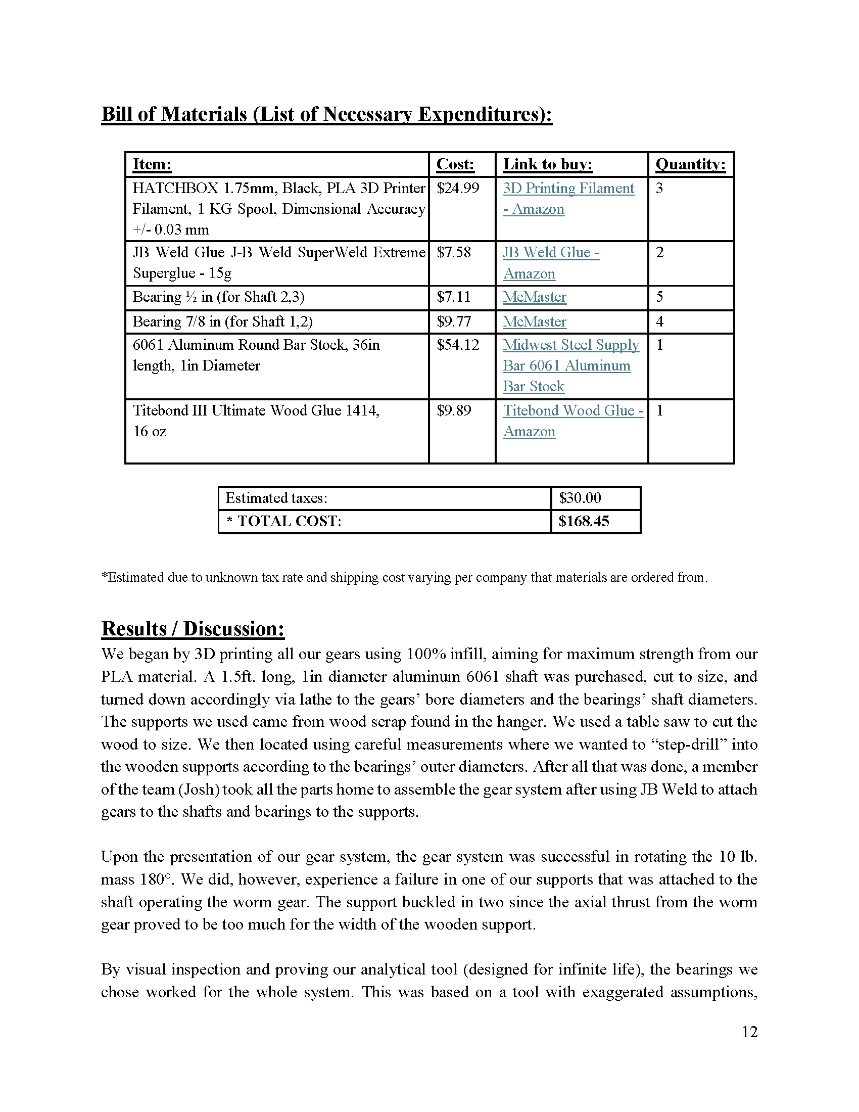
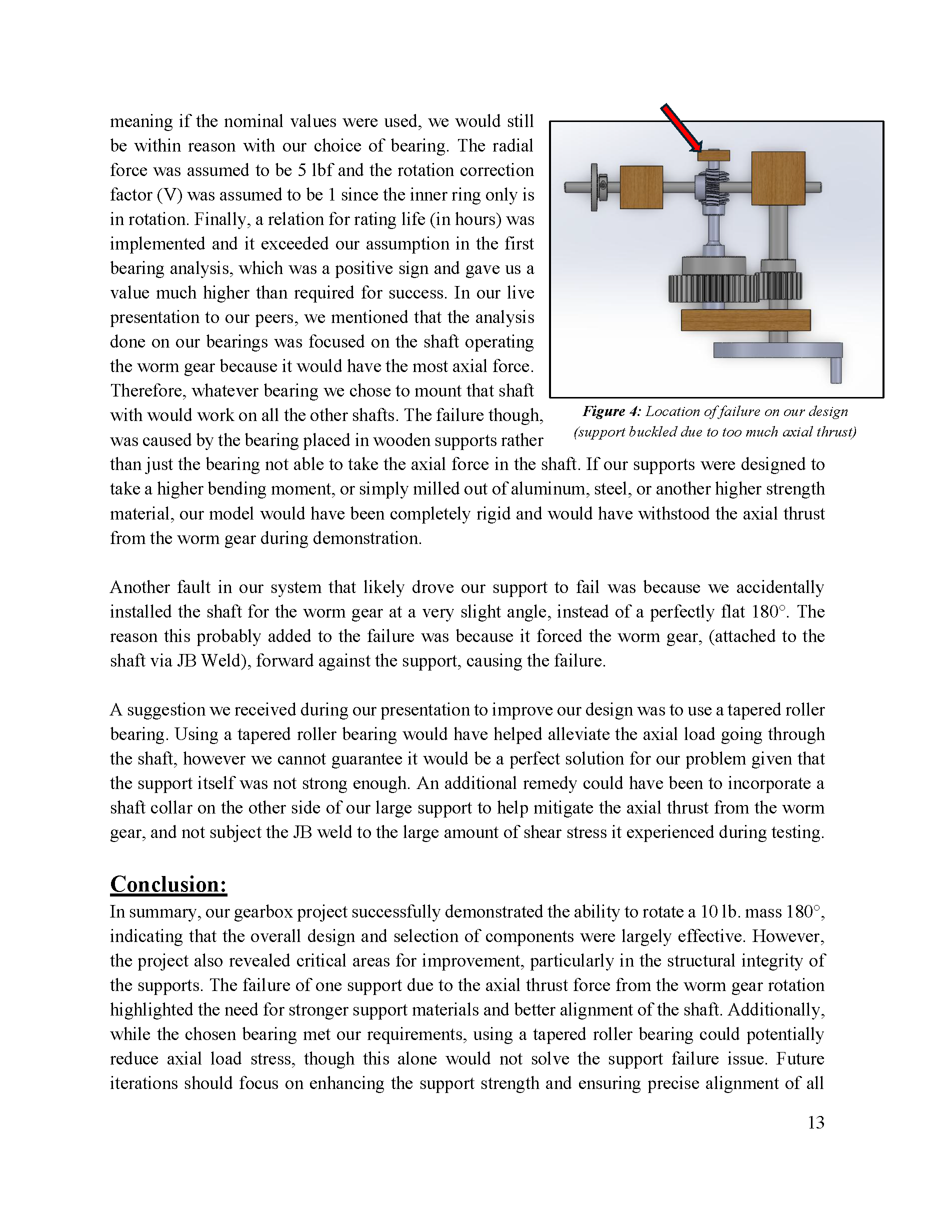
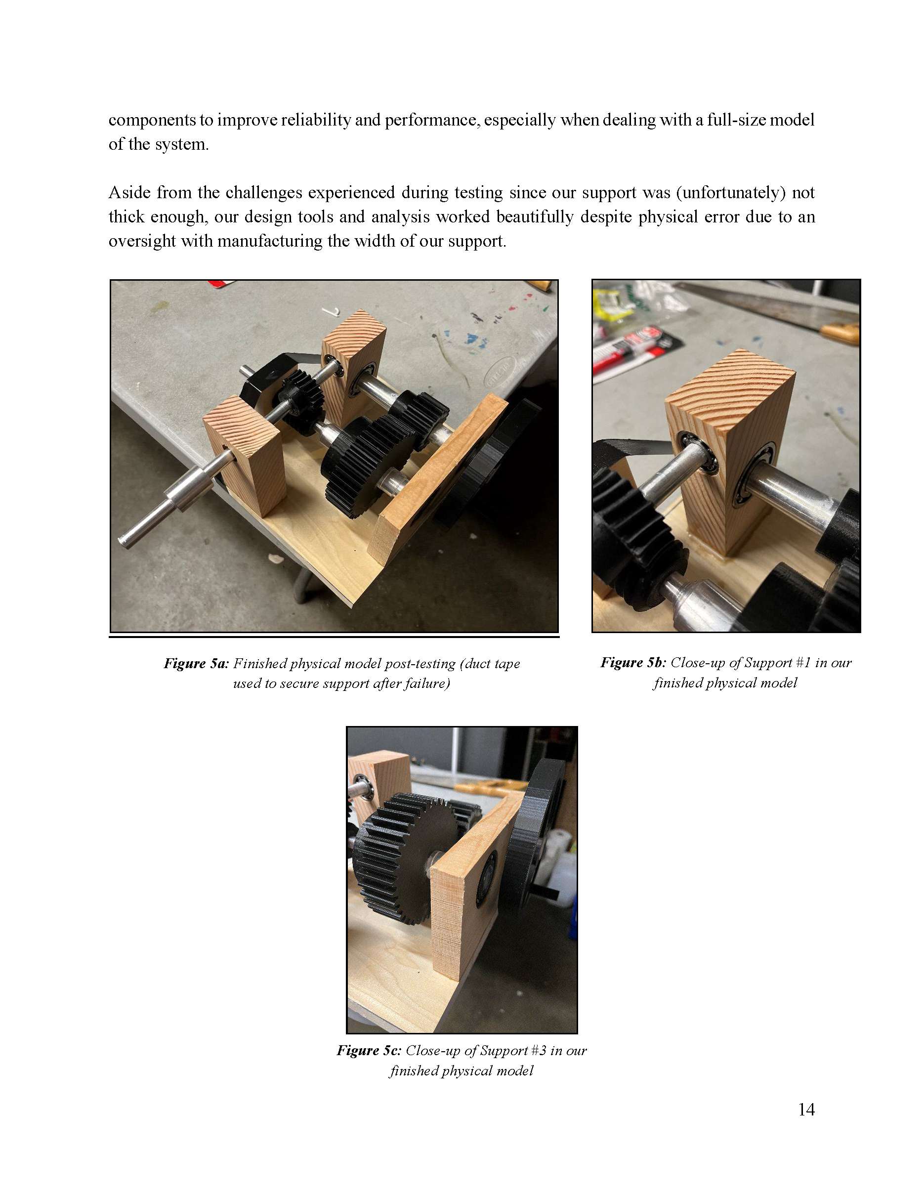
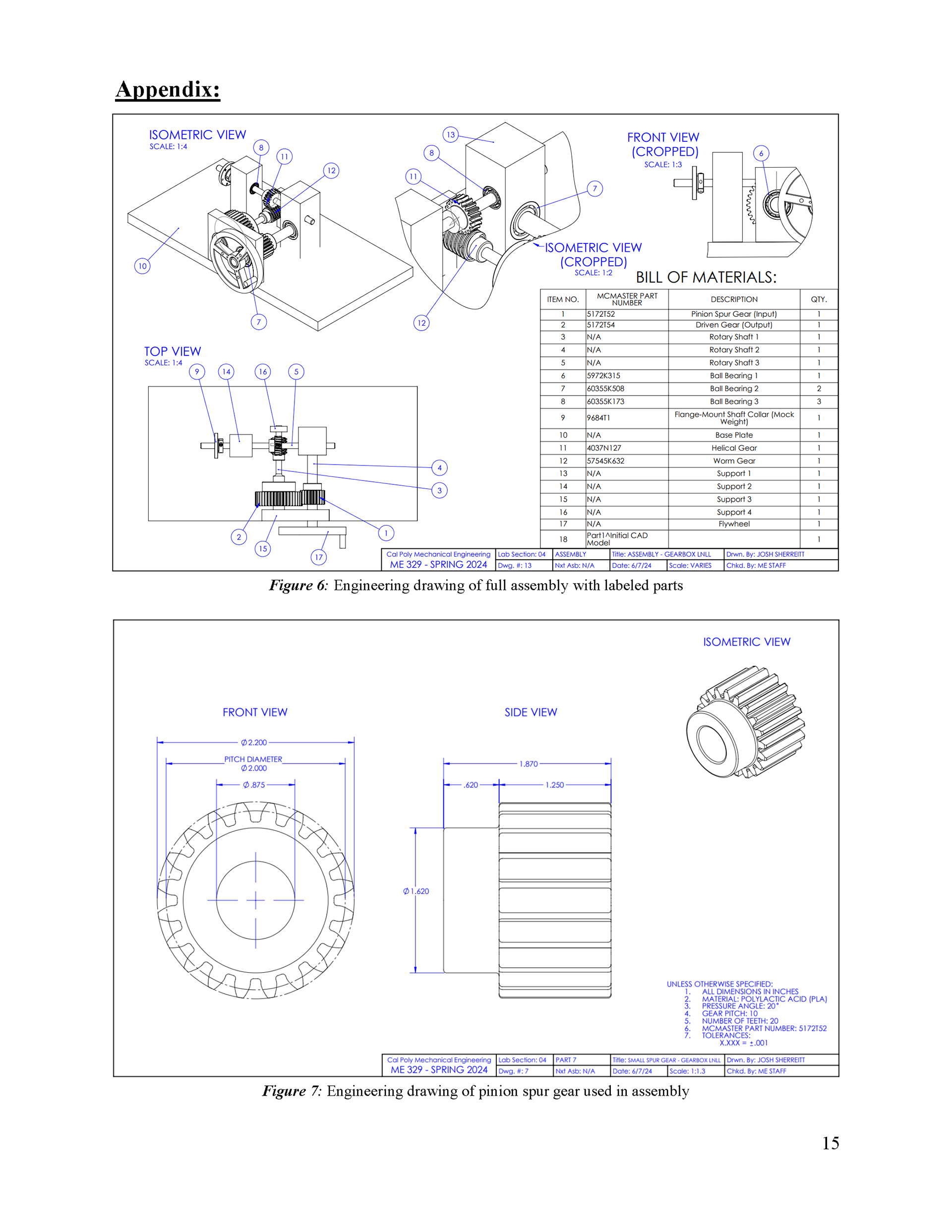
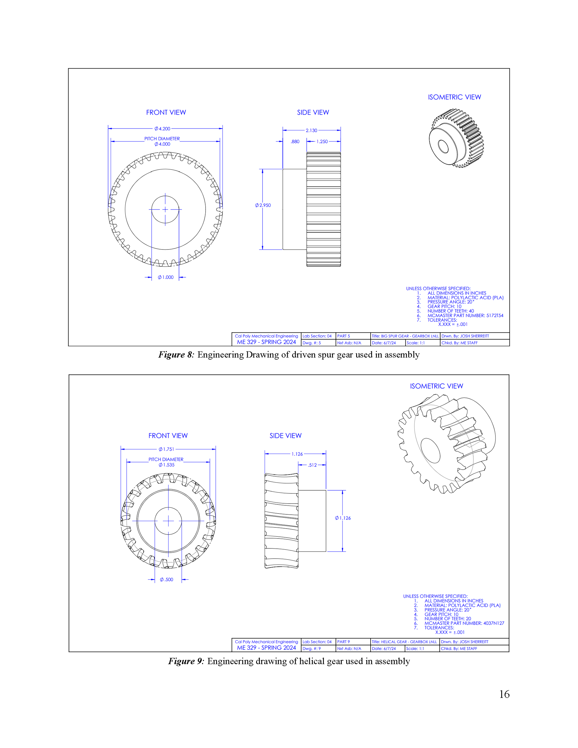
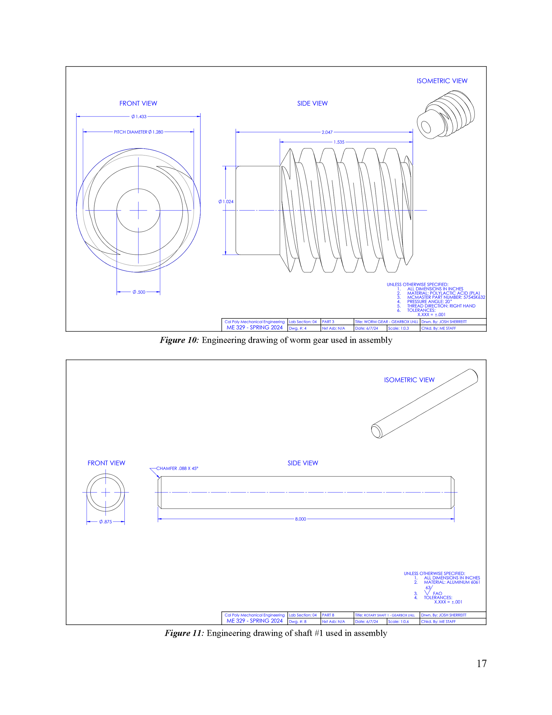
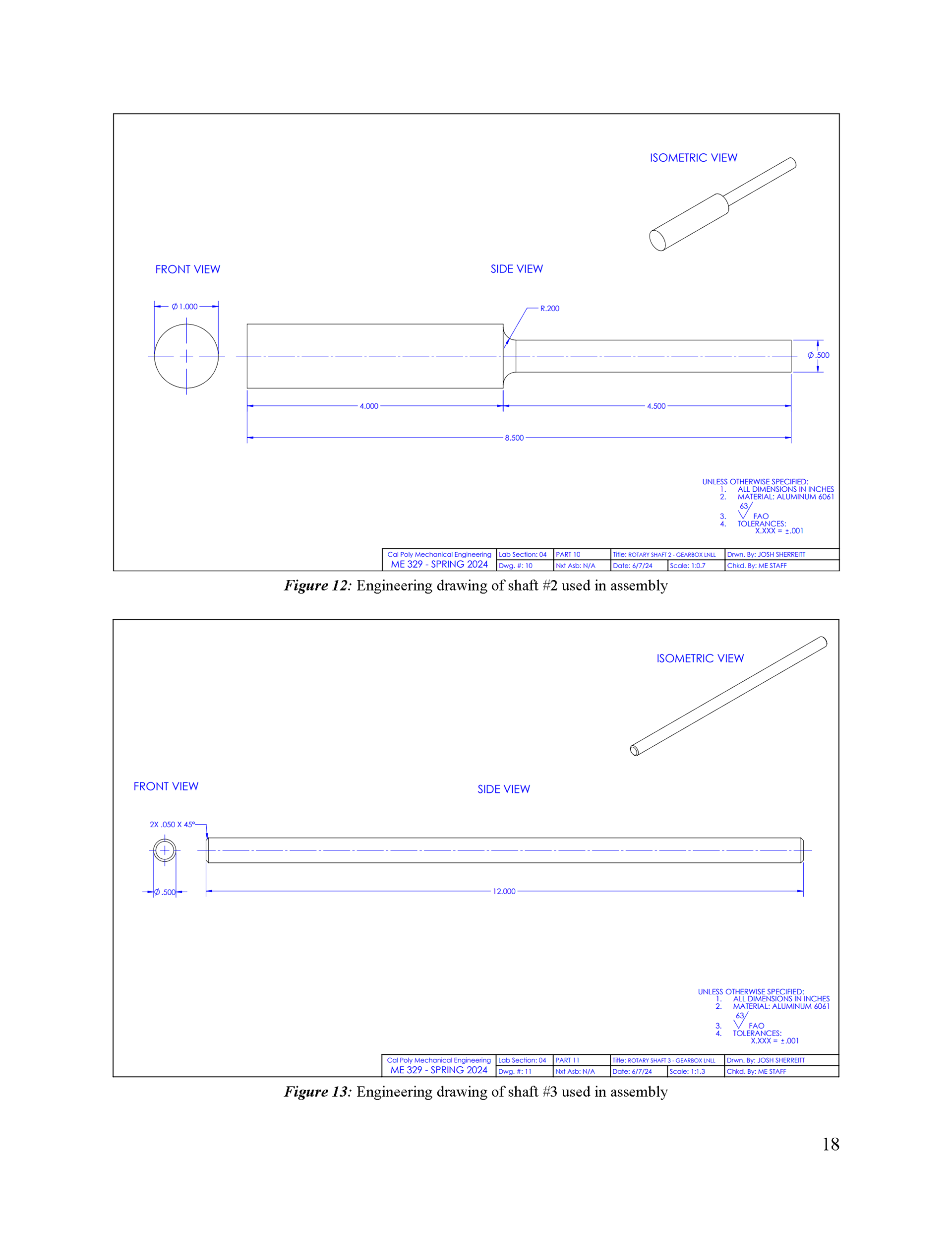
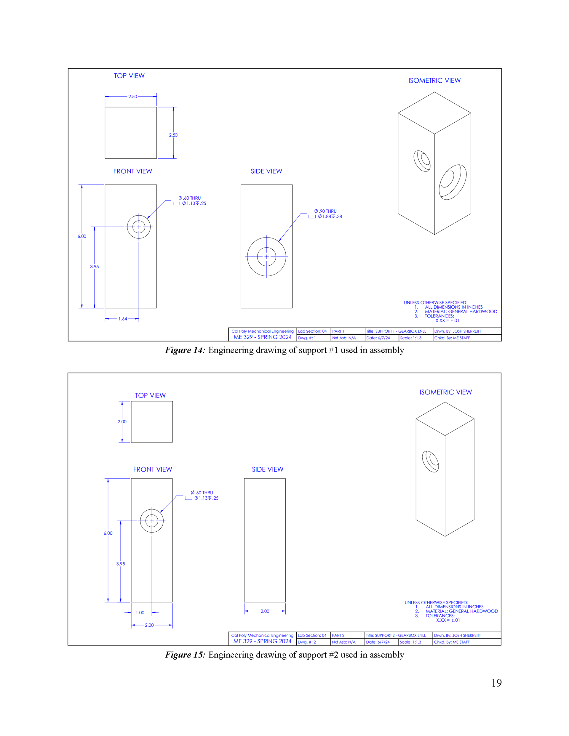
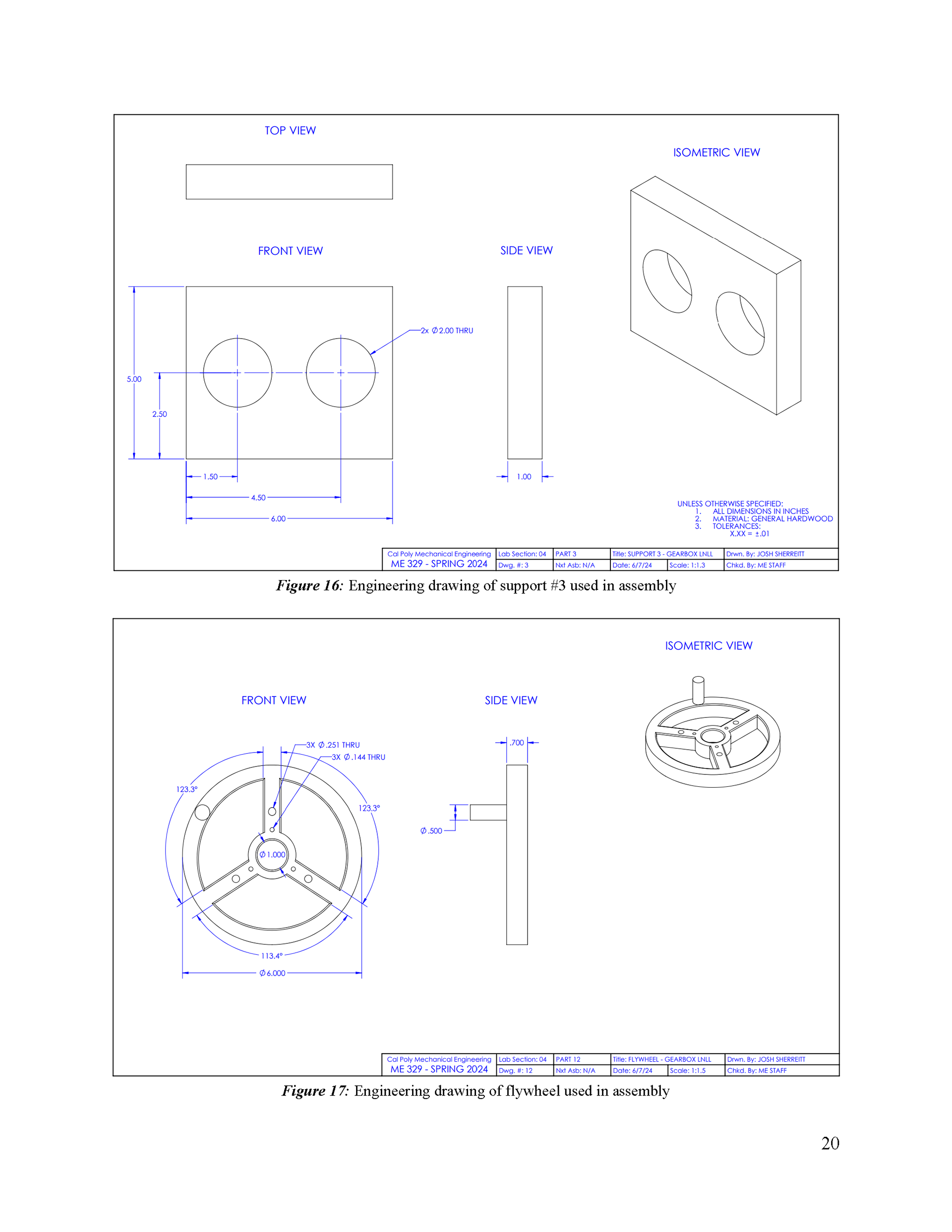
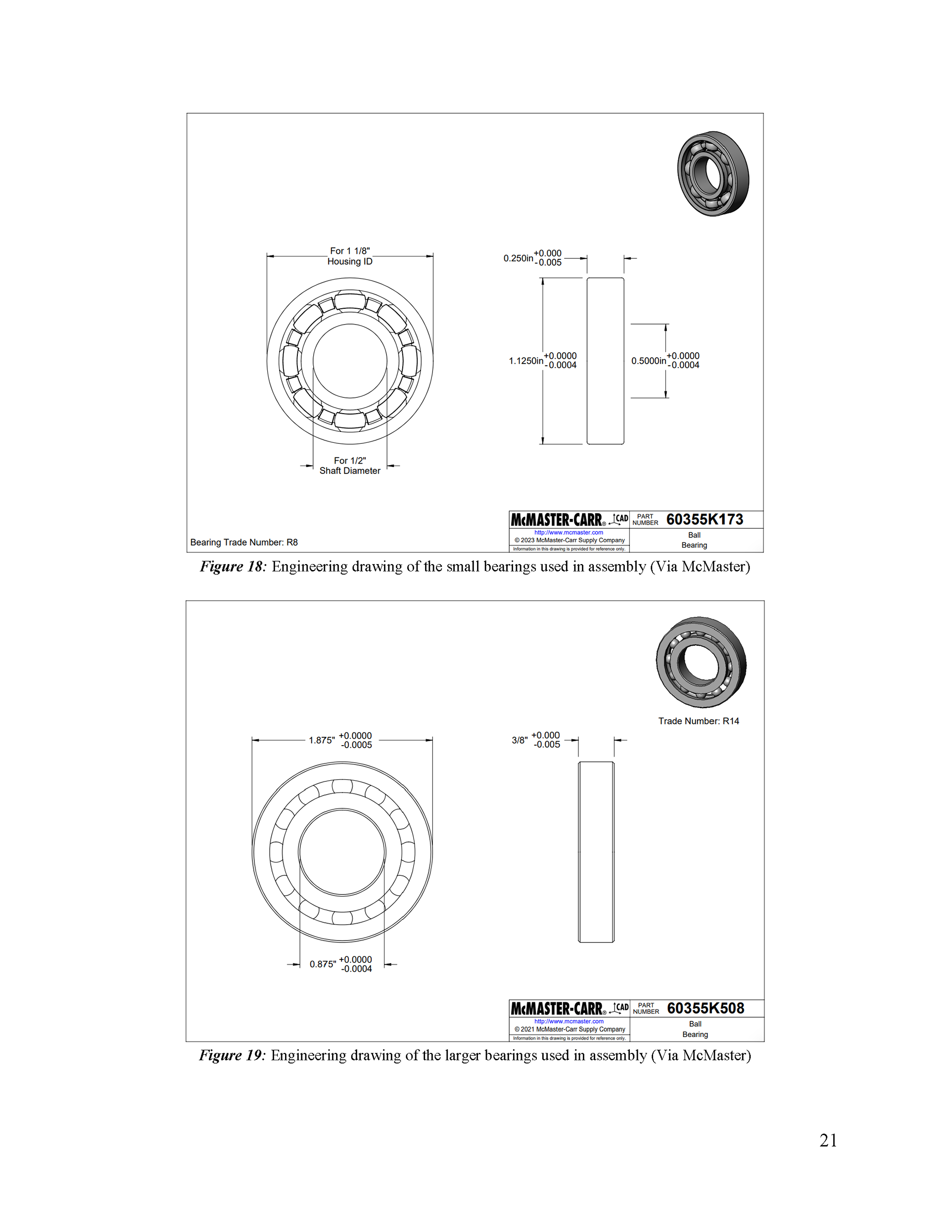
The images above are from ME-329 "Design for Strength and Stiffness II" Laboratory class, taught by Dr. Alan Zhang. In this lab, my lab mates and I were tasked with designing a gearbox capable of converting a 10-lbf, 60 RPM input force into a torque able to lift a 10-lbm weight on a 6-inch arm at approximately 3 RPM and to prevent backdrive. We were then asked to scale this to a larger application with a 120-kg weight. To accomplish these tasks, we designed a system utilizing a 3D-printed worm gear and spur gear subsystem.
The report, hand calculations, MATLAB gear design code, and following analysis for this Gearbox Project in ME-329 "Design for Strength and Stiffness II" Laboratory class is shown on the right. My lab mates (Sam Sakaguchi, Roy Guptill, and Gage Heinze) and I were able to successfully create a gearbox meeting the design requirements and demonstrate this live to the class and our professor.
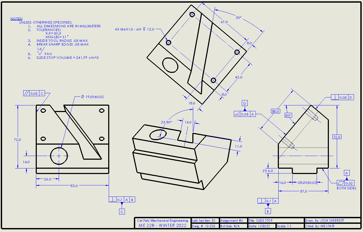
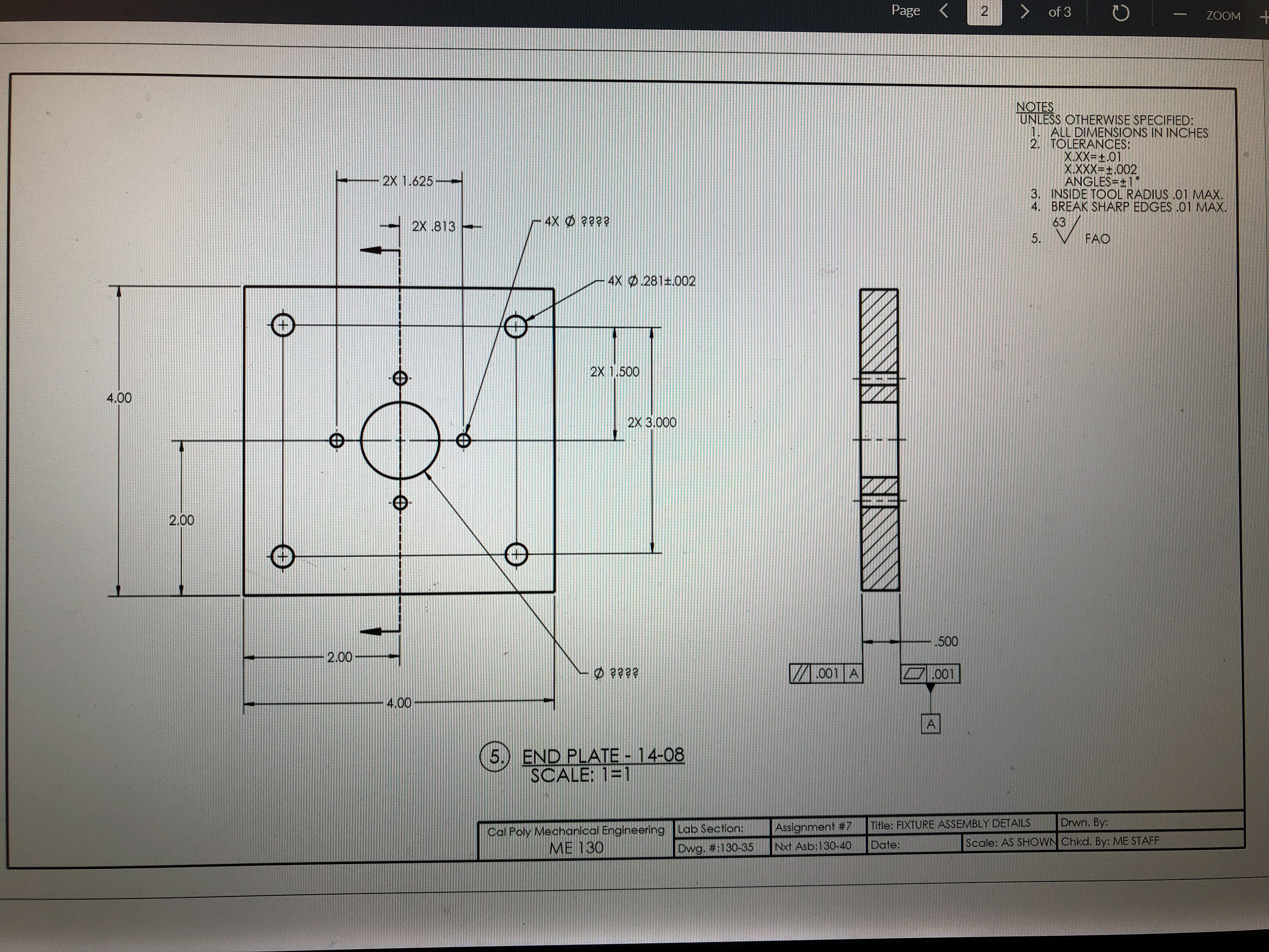
These SolidWorks drawings were projects from my ME-228 and ME-130 "Engineering Design Communication" Laboratory class, taught by Professor Ashley Leitzell. In this class, we were required to use SolidWorks, GD&T tools, and dimensioning and tolerancing industry standards to create drawings for machining and assembly.
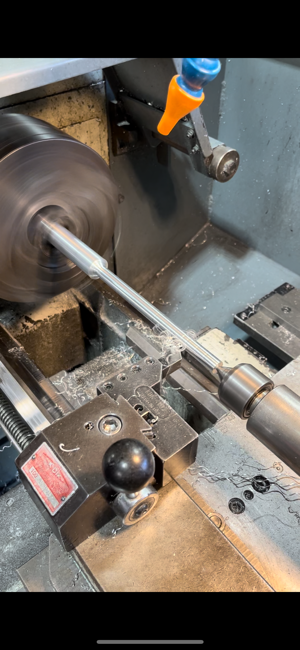
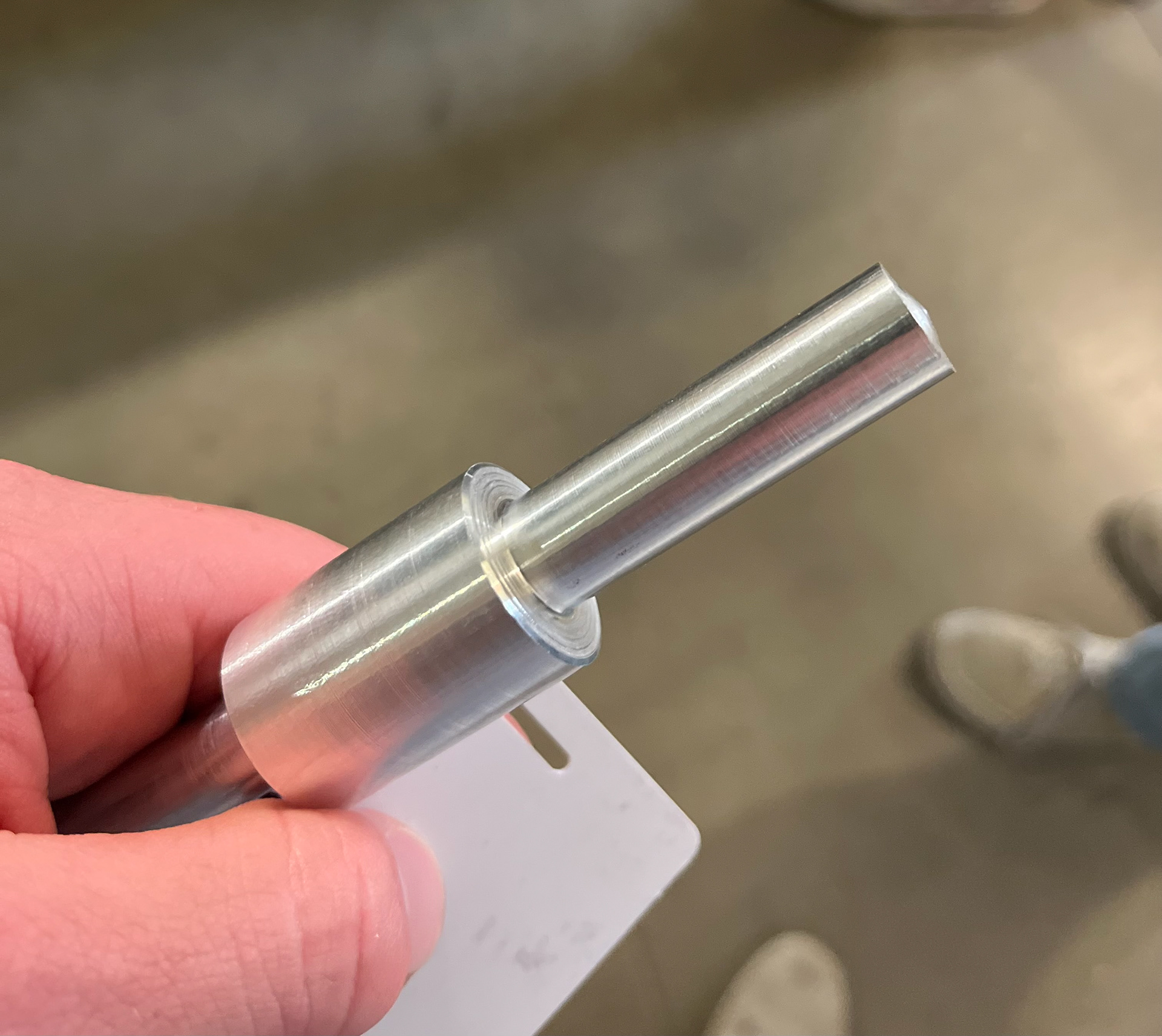
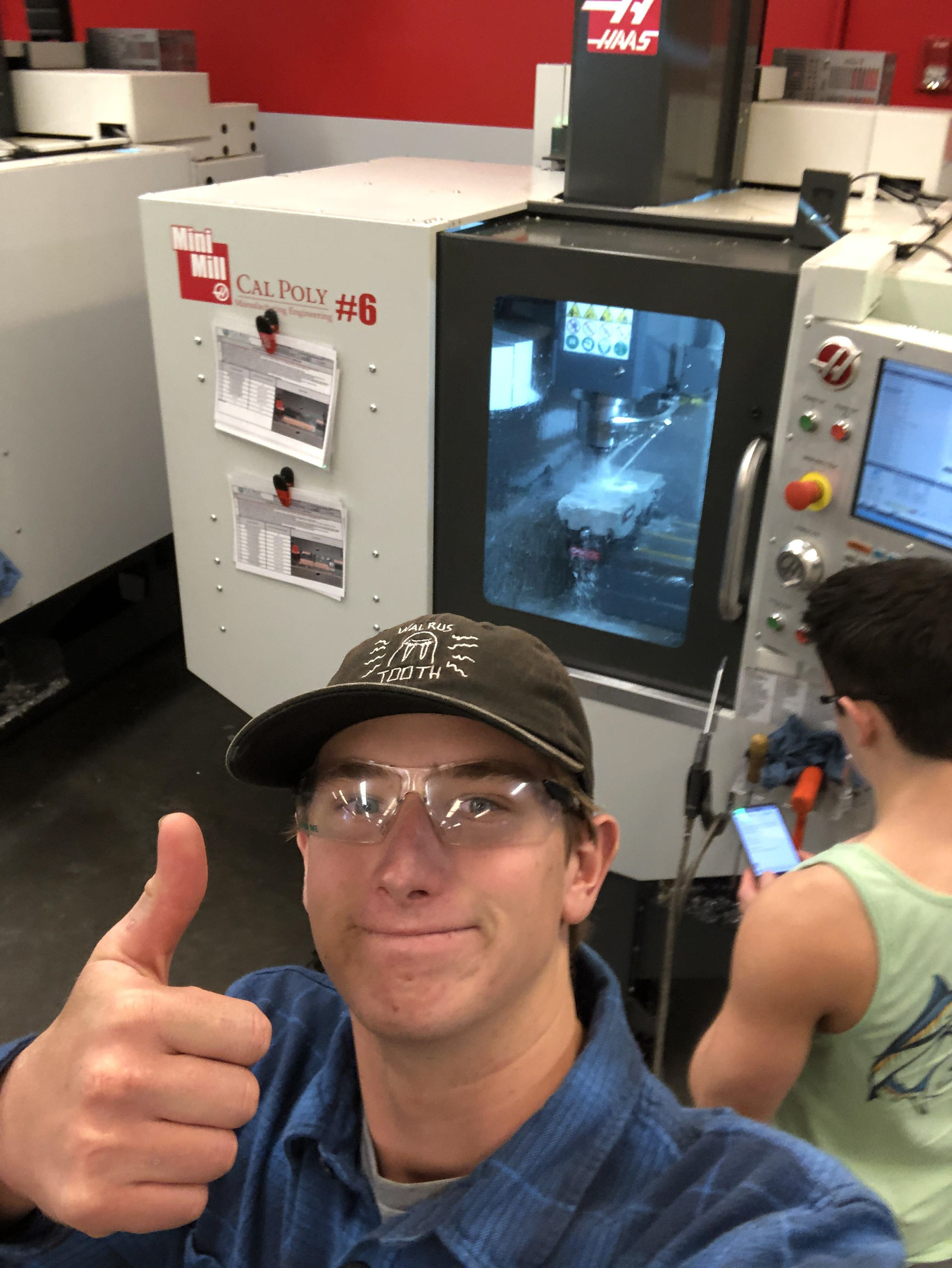
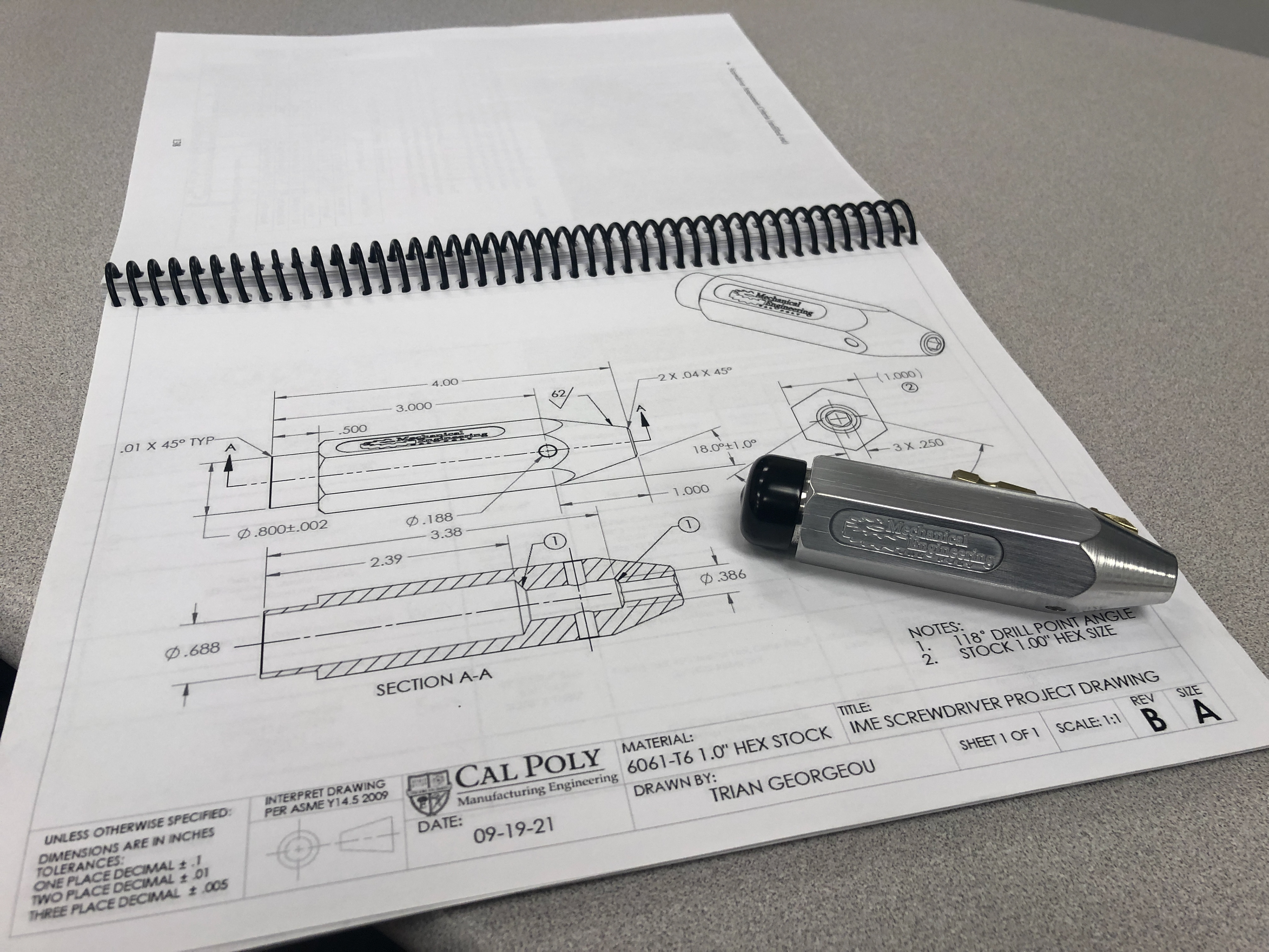
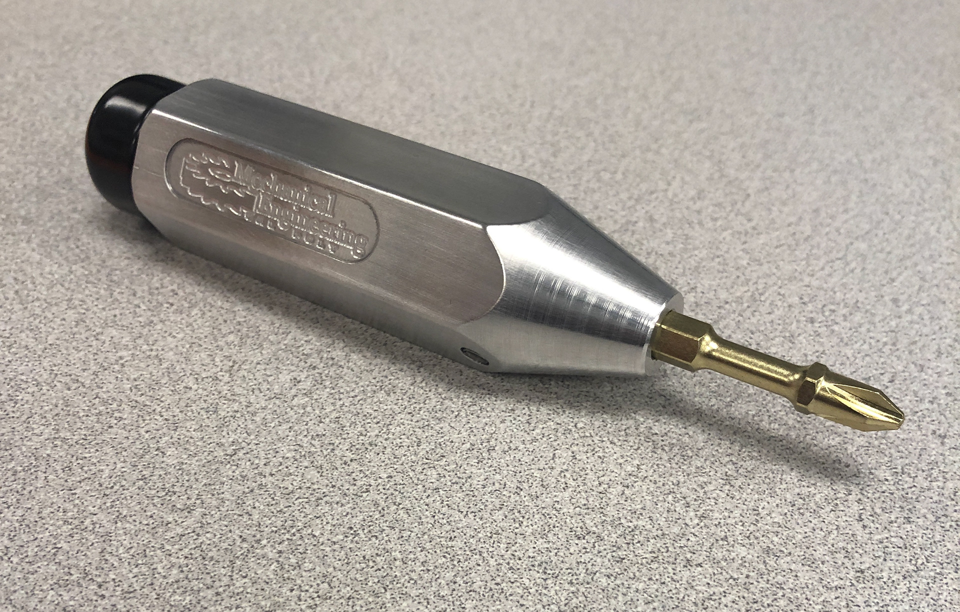
These images were from a project in which I machined a fully functional screwdriver in IME-142 "Manufacturing Processes: Material Removal," taught by Professor Trian Georgeou. We utilized LeBlond lathes for turning operations and Haas VF-2 3-axis mills to complete the required operations for this project.
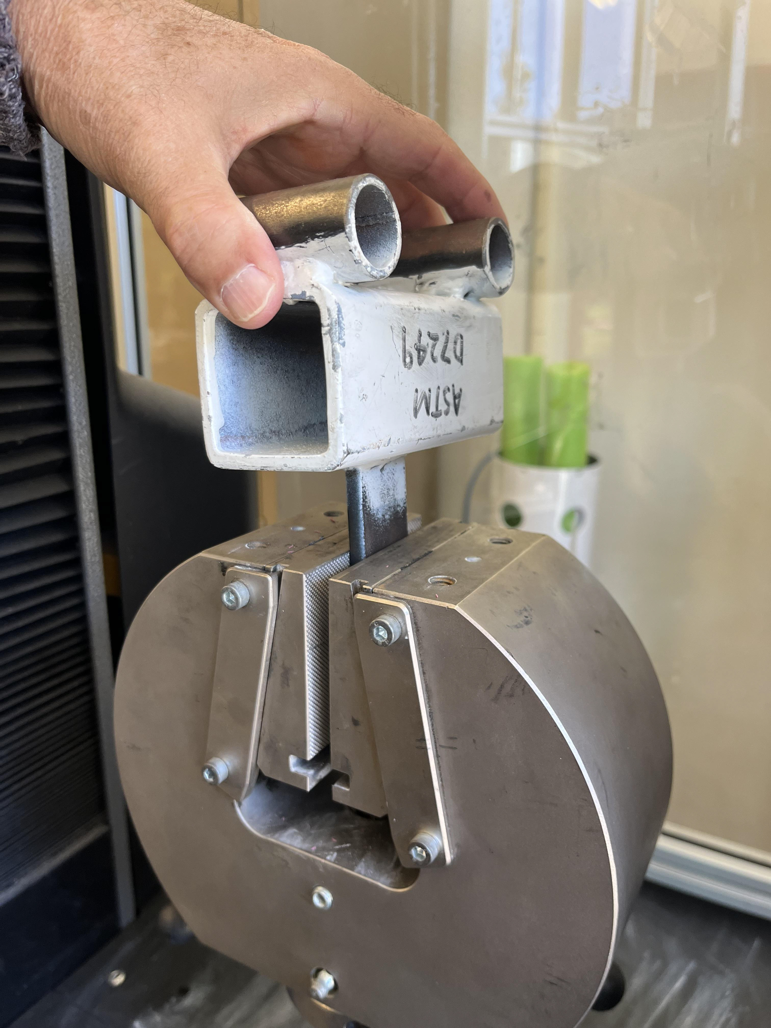
This image is testing a piece for fit in an Instron Tensile Test Machine, for finding the yield strength and ultamite strength of the steel bar stock.
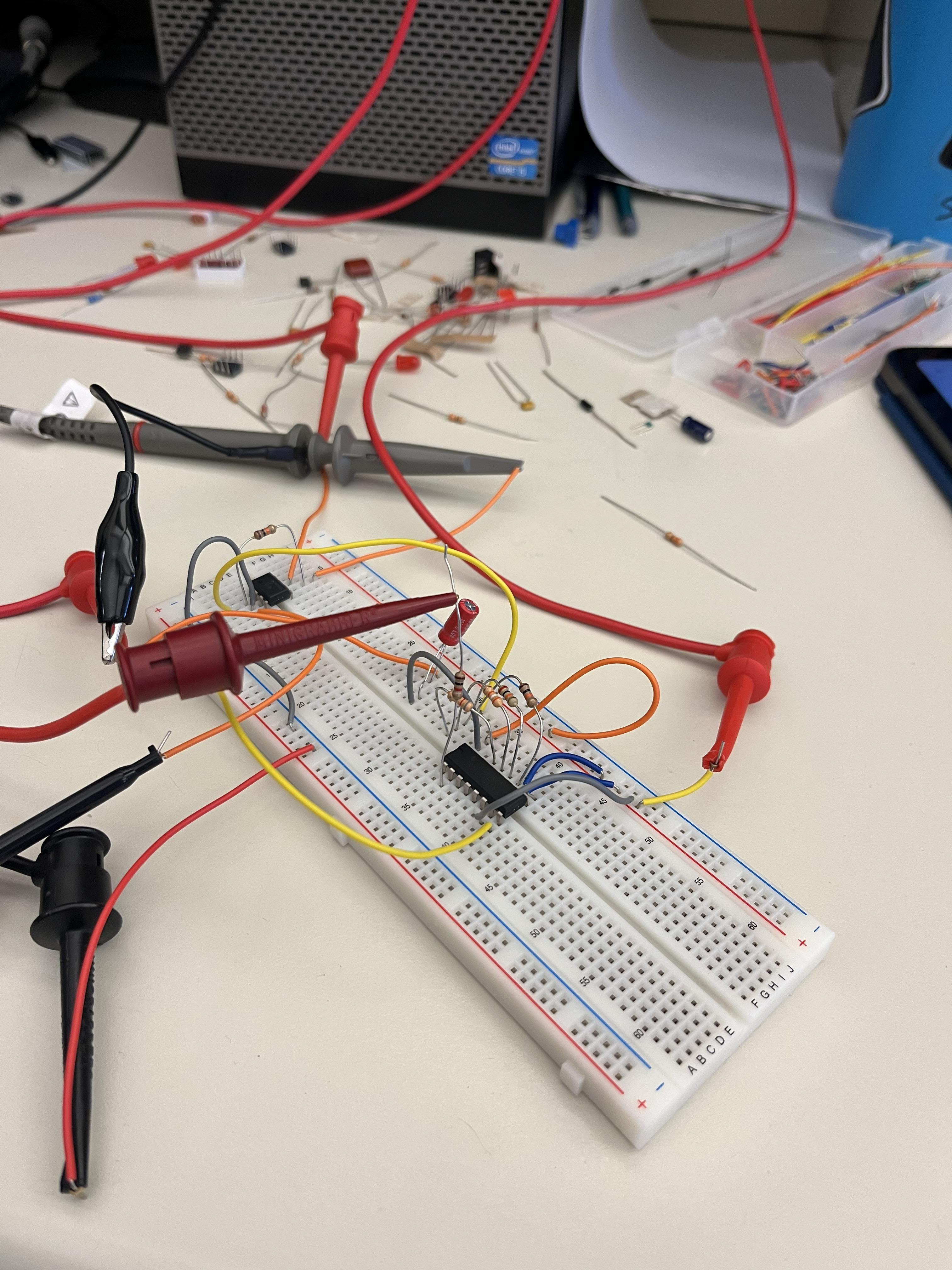
This image was from EE-361 "Electronics" Labratory class, taught by Professor Noel Ellis. In the image on the left, I was using a clock pulse input to model and then record the sinusoidal output for a lab.
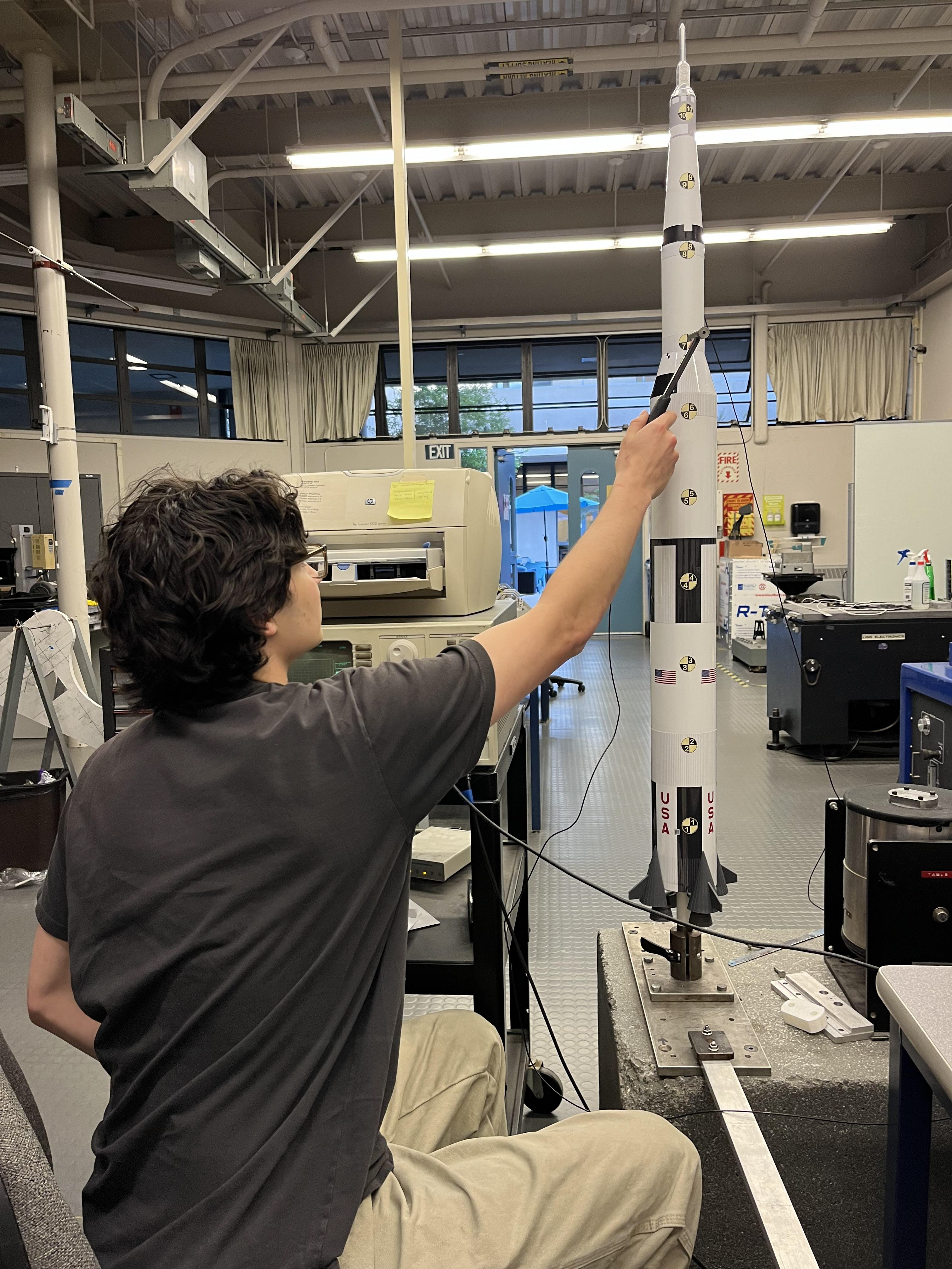
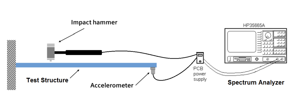
These images were also from my ME-318 "Mechanical Vibrations" Laboratory class. The first image shows the use of a load cell and oscilloscope to determine the natural frequency of a Boeing 777 model airplane. The second and third images depict finding the resonant frequency of a 1/50th scale Saturn V Apollo rocket using a modal impact hammer test.
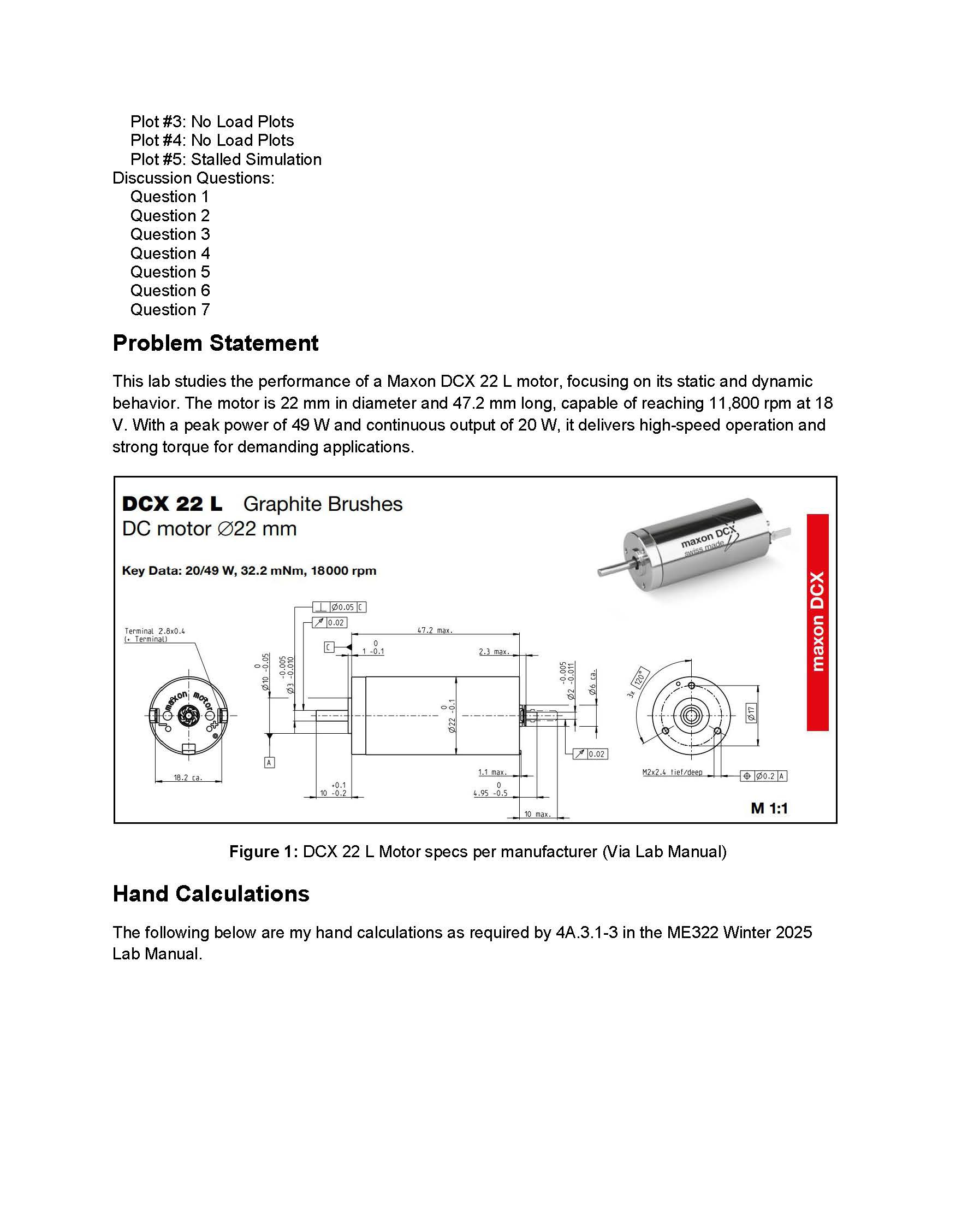
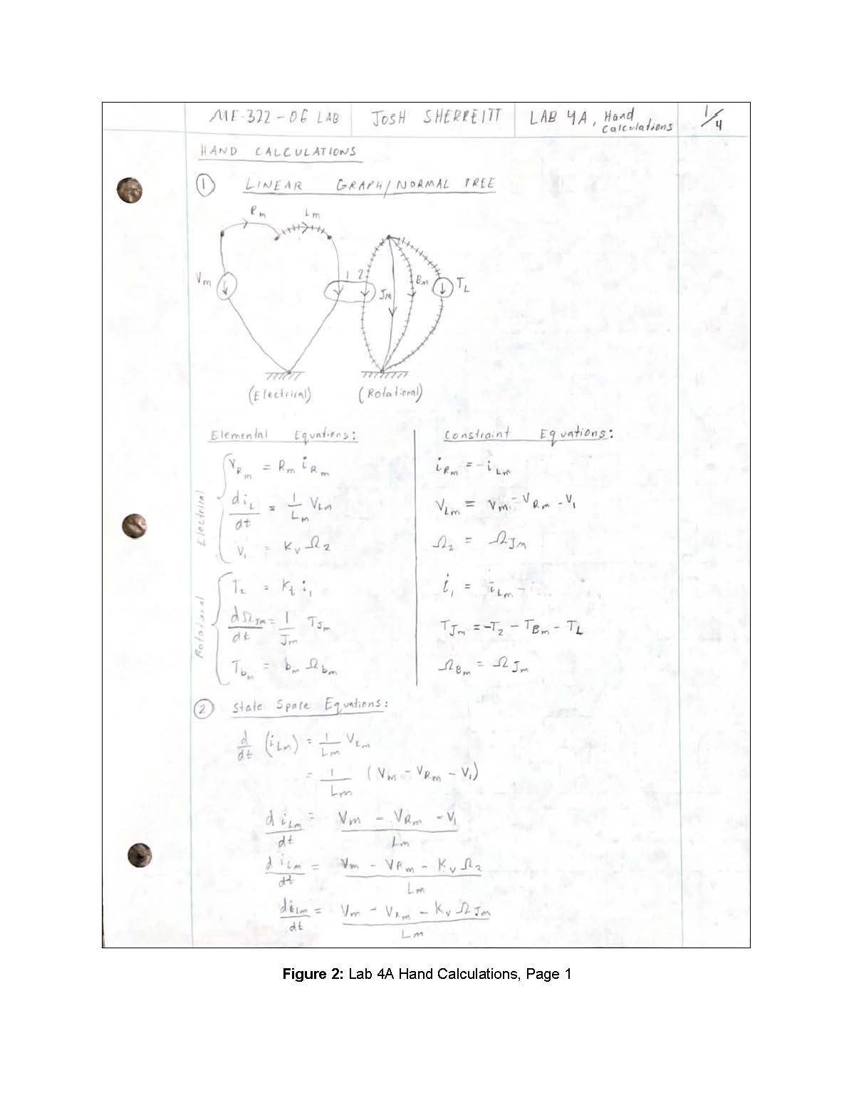
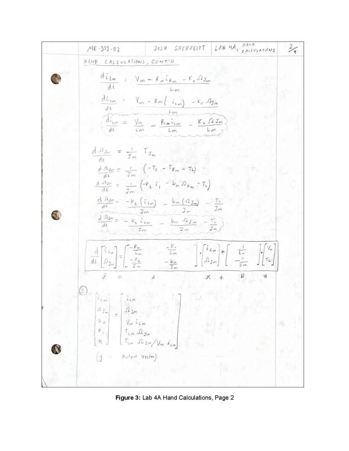
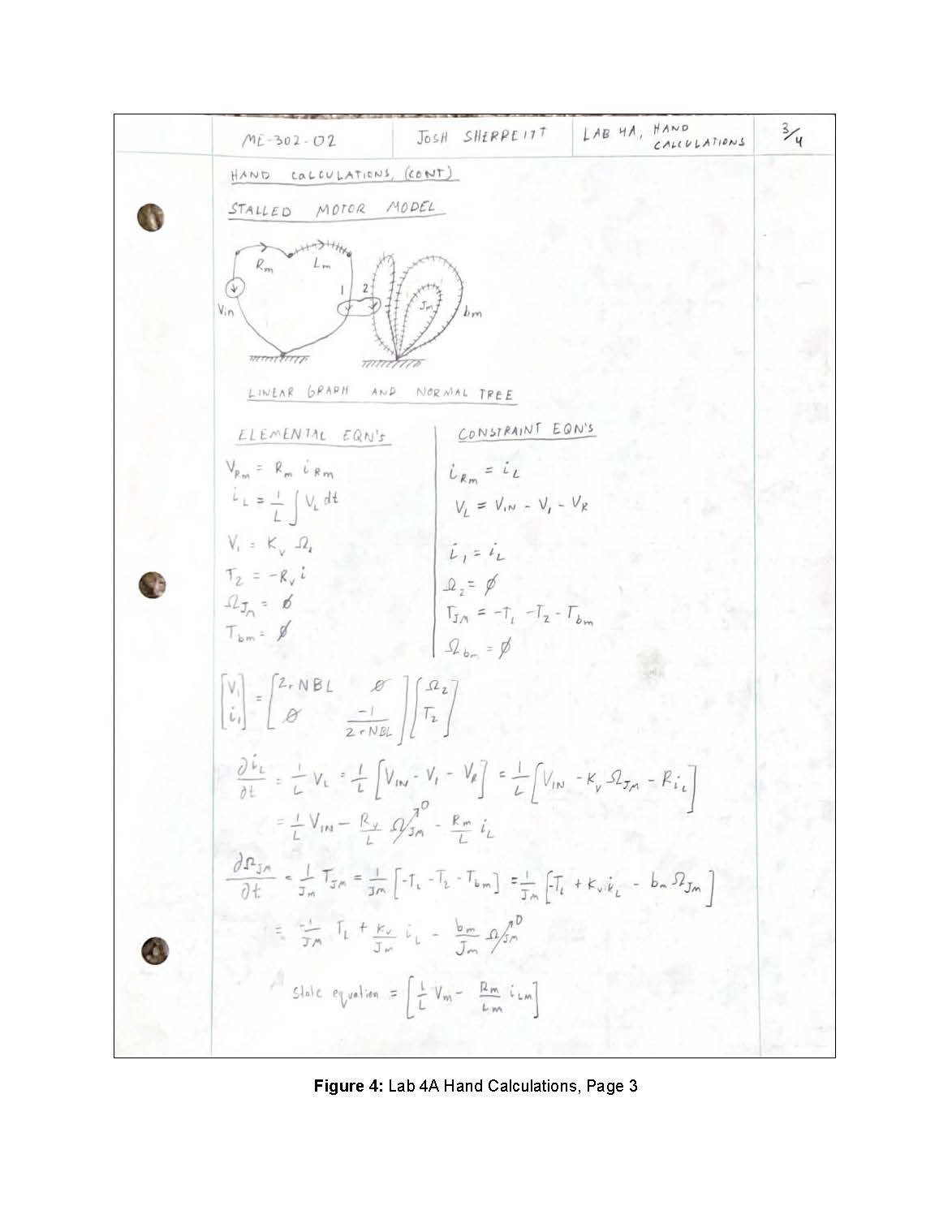
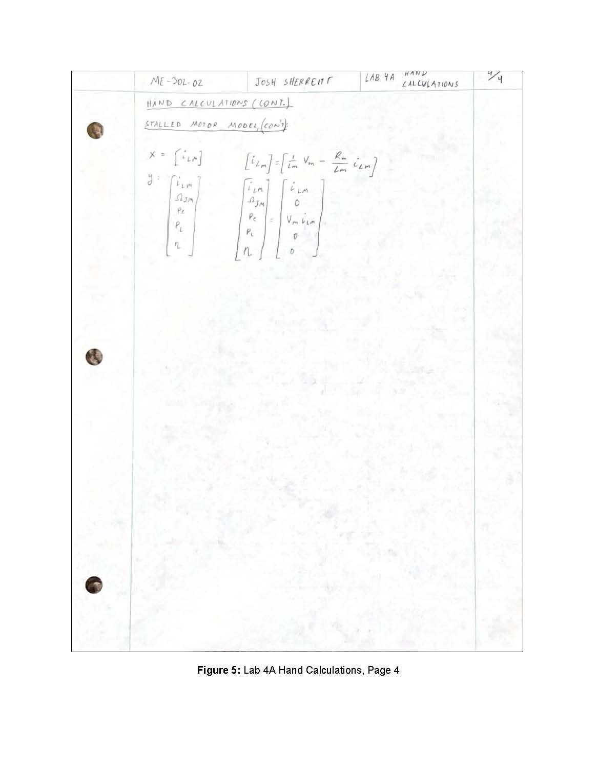
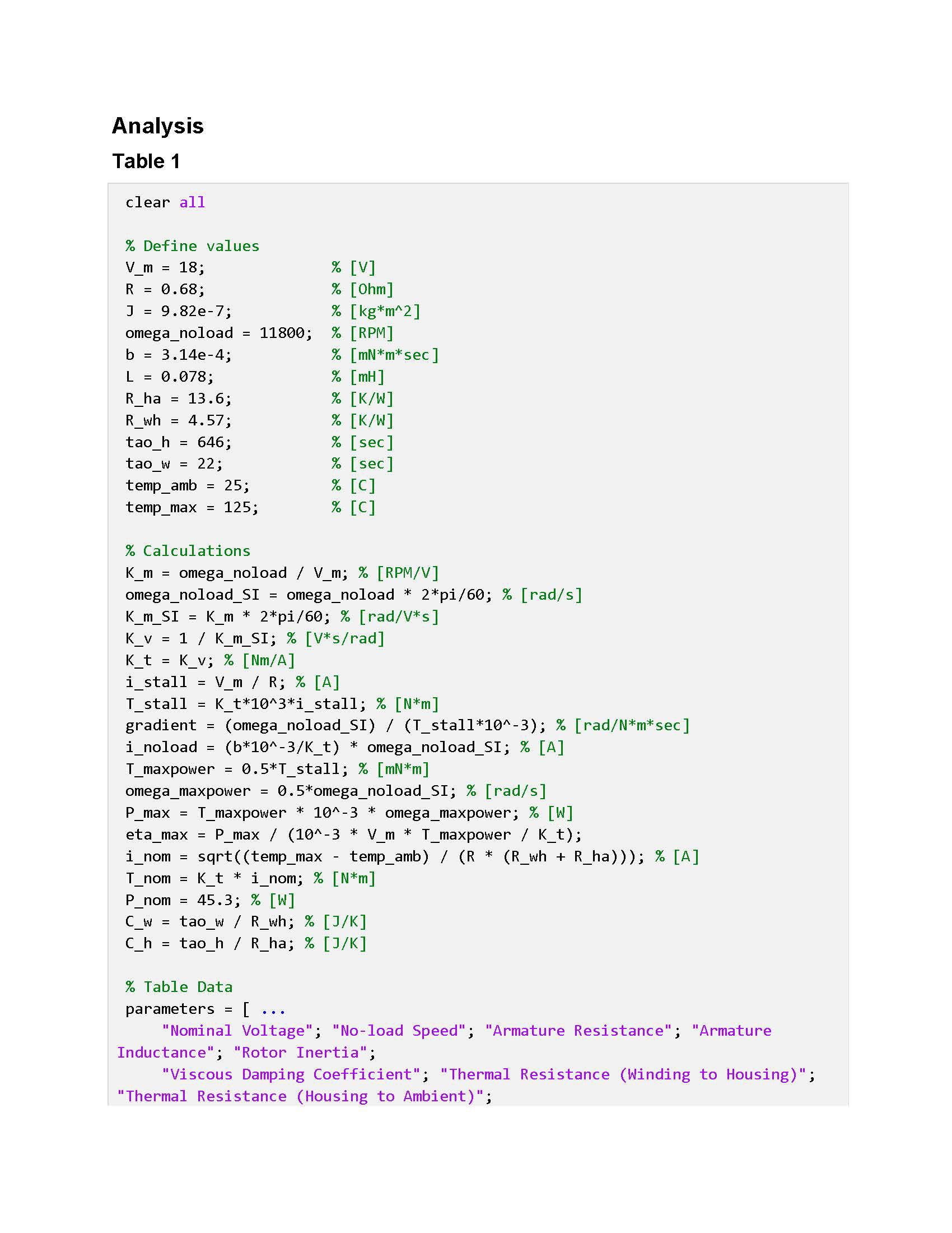
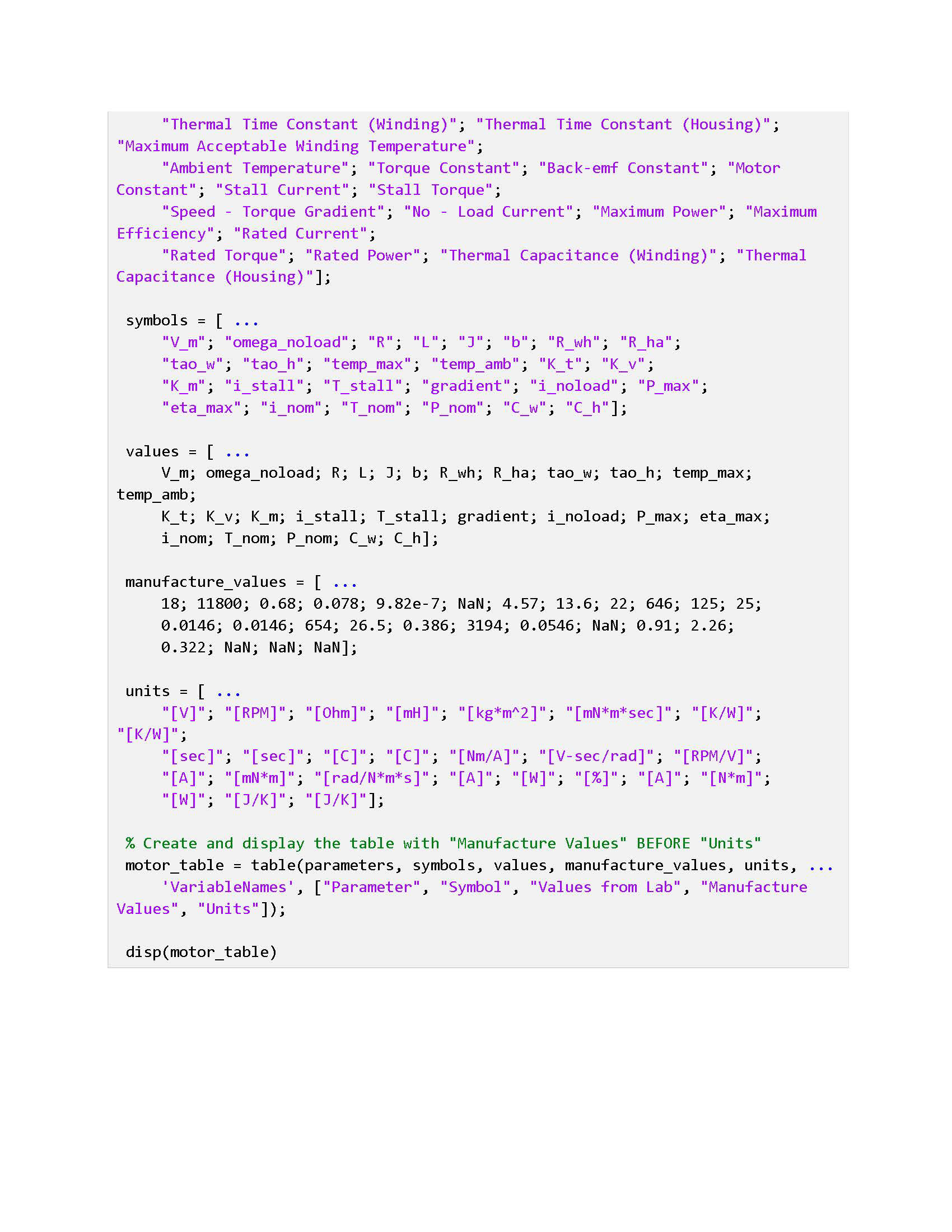
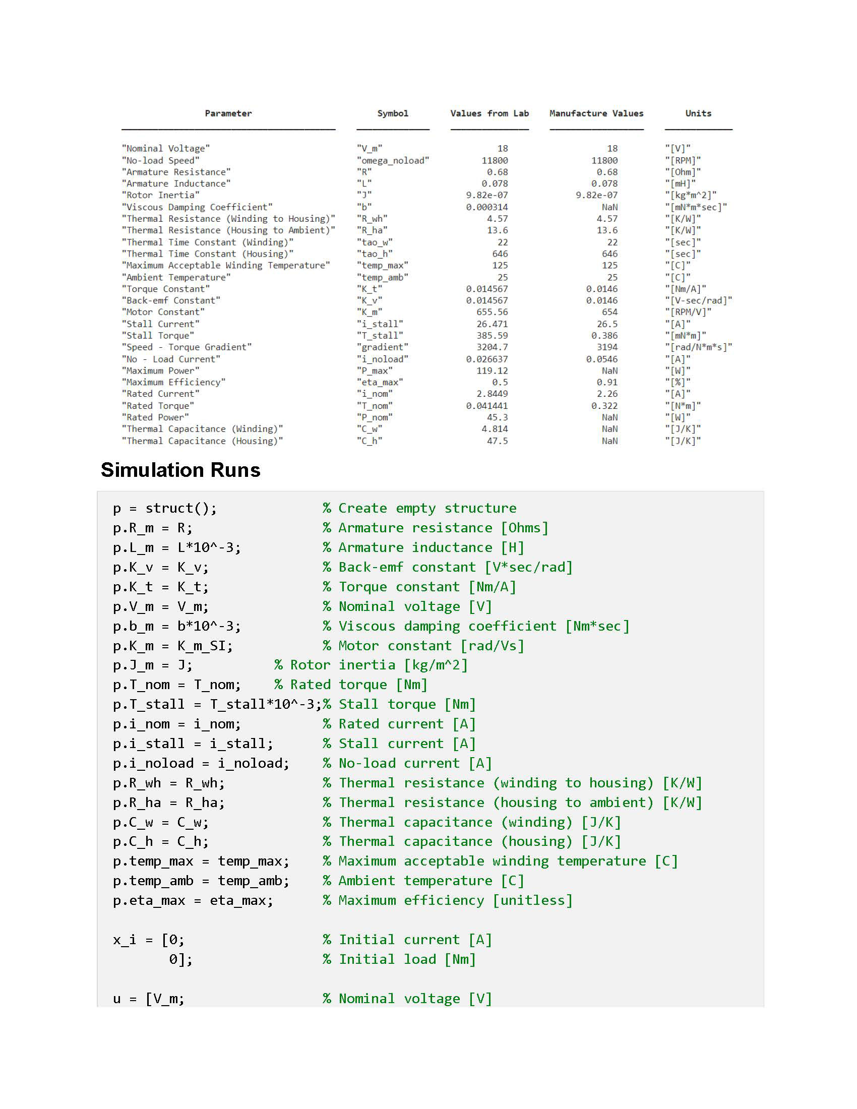
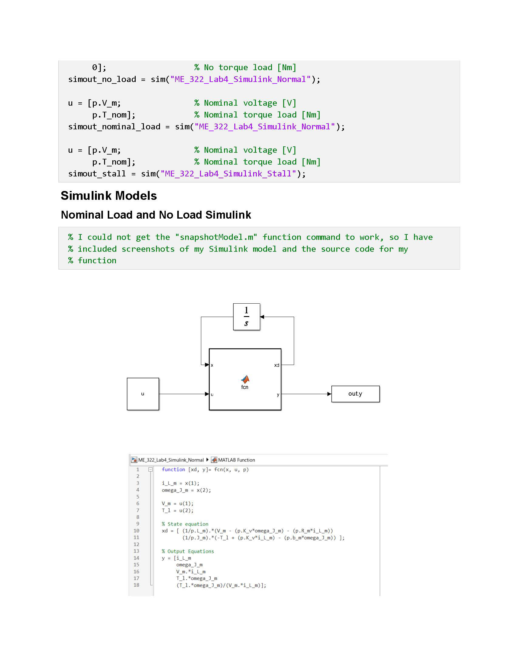
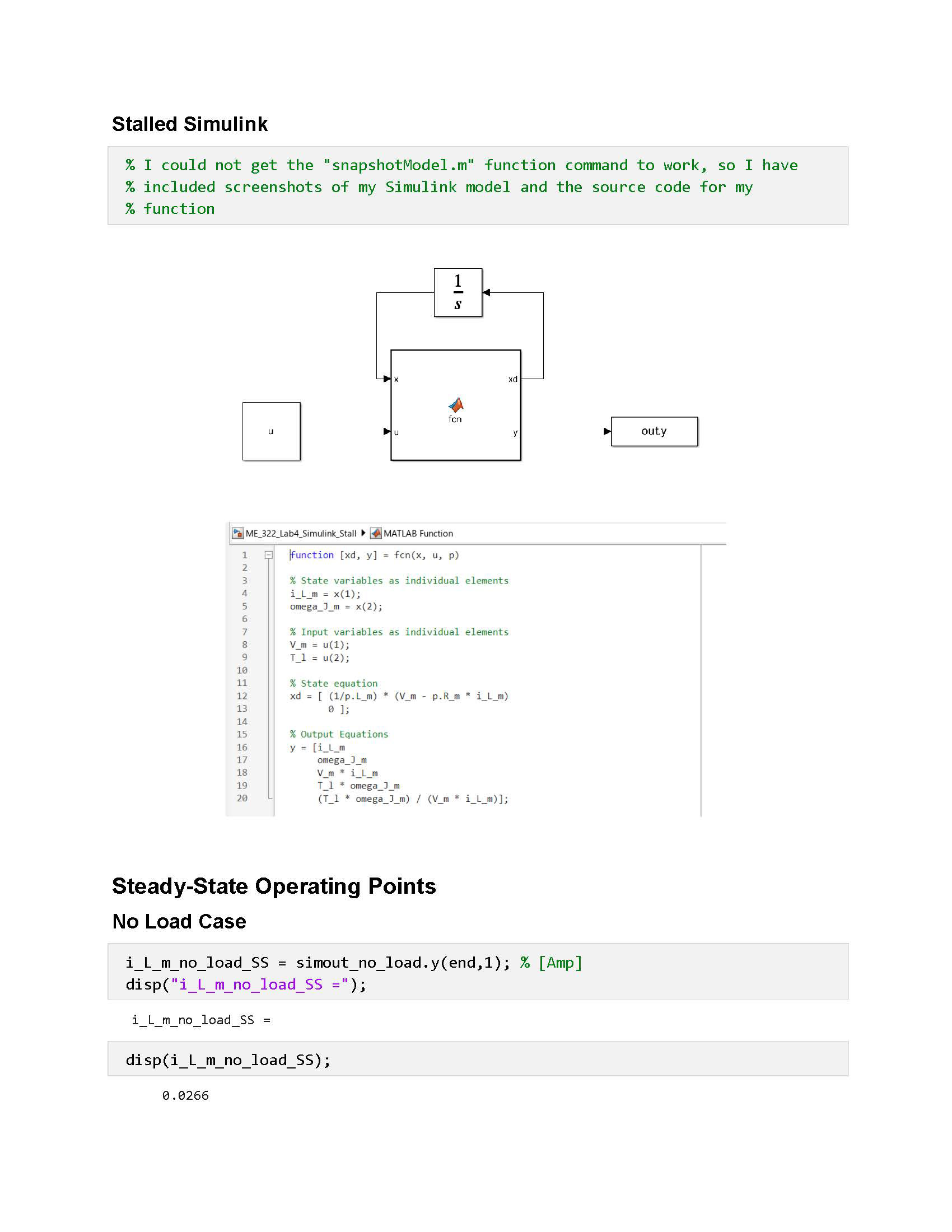
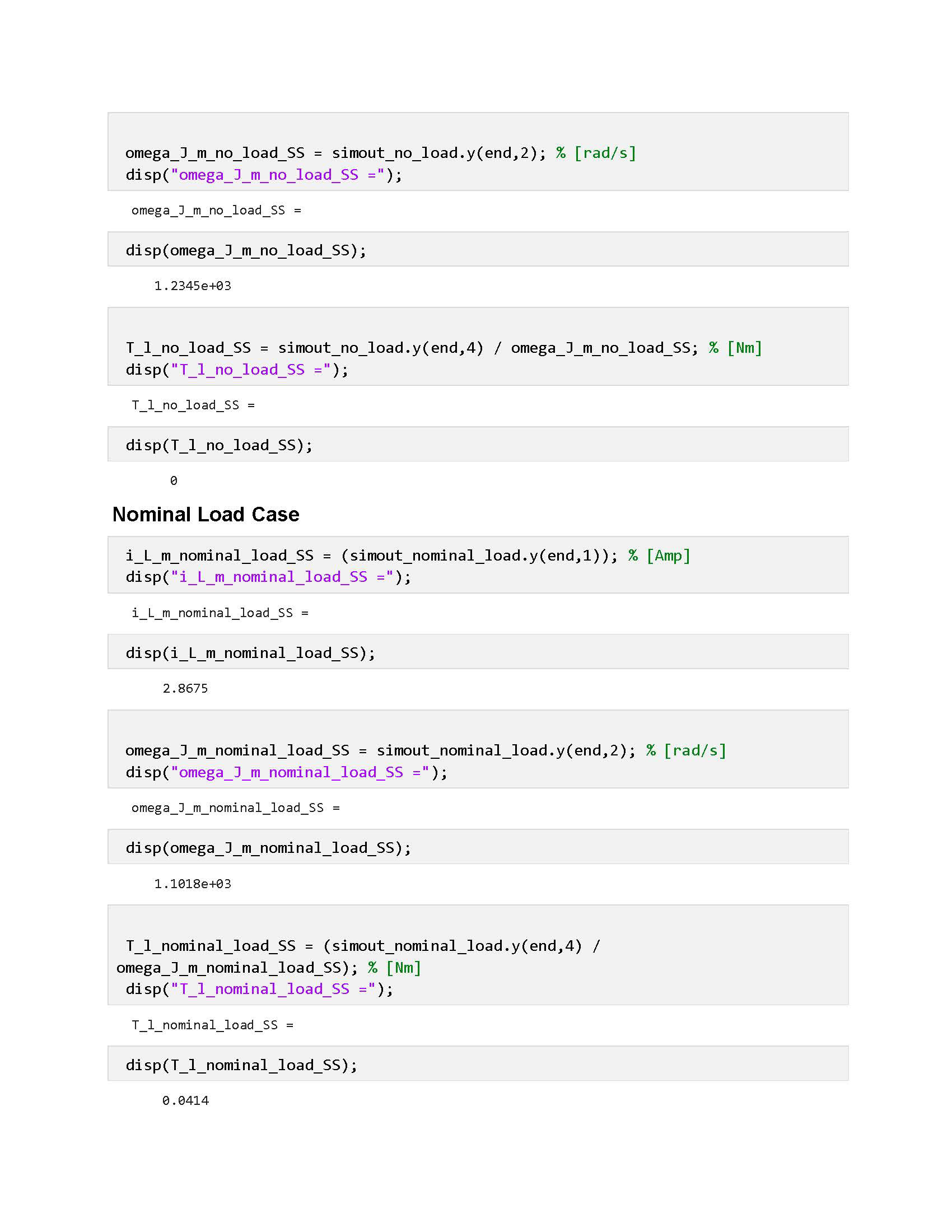
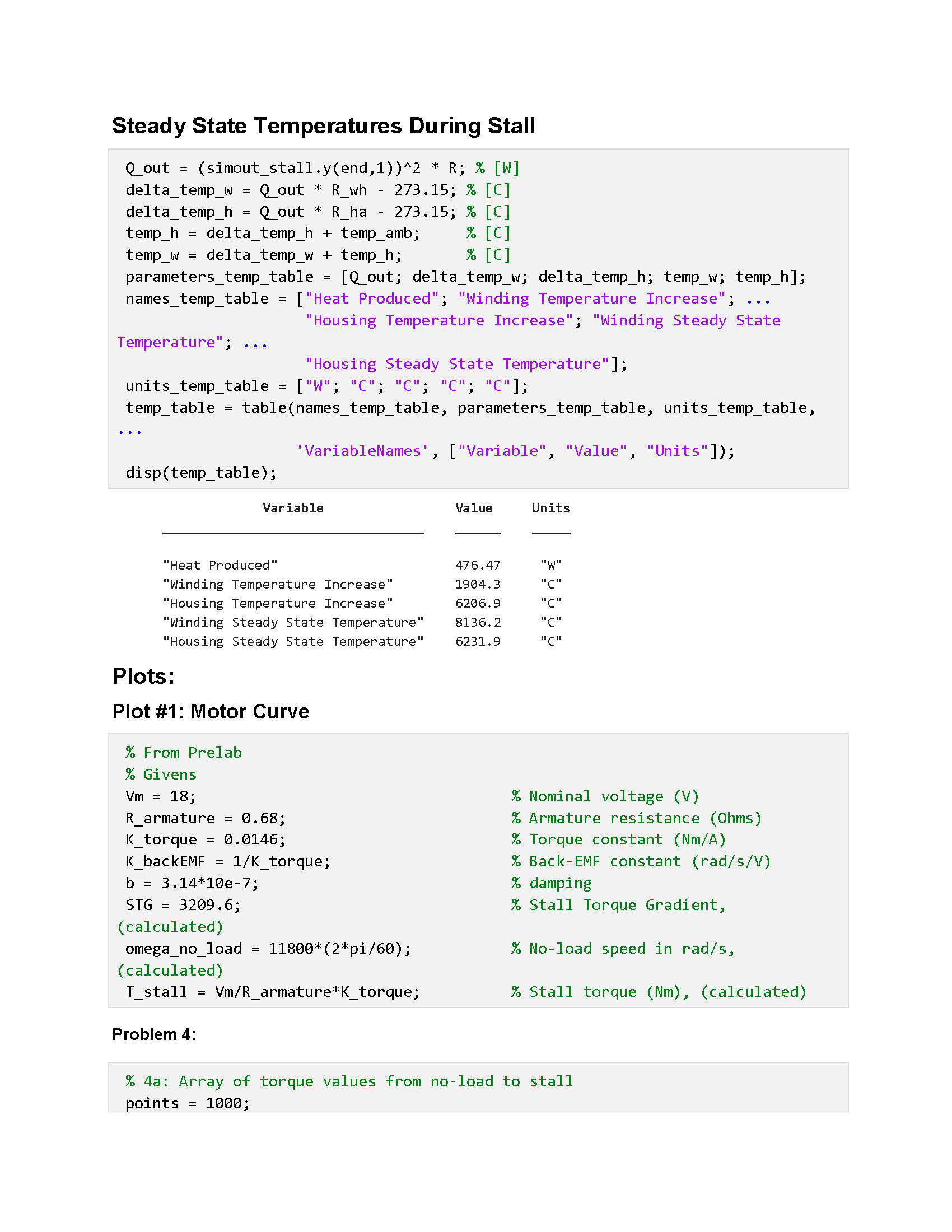
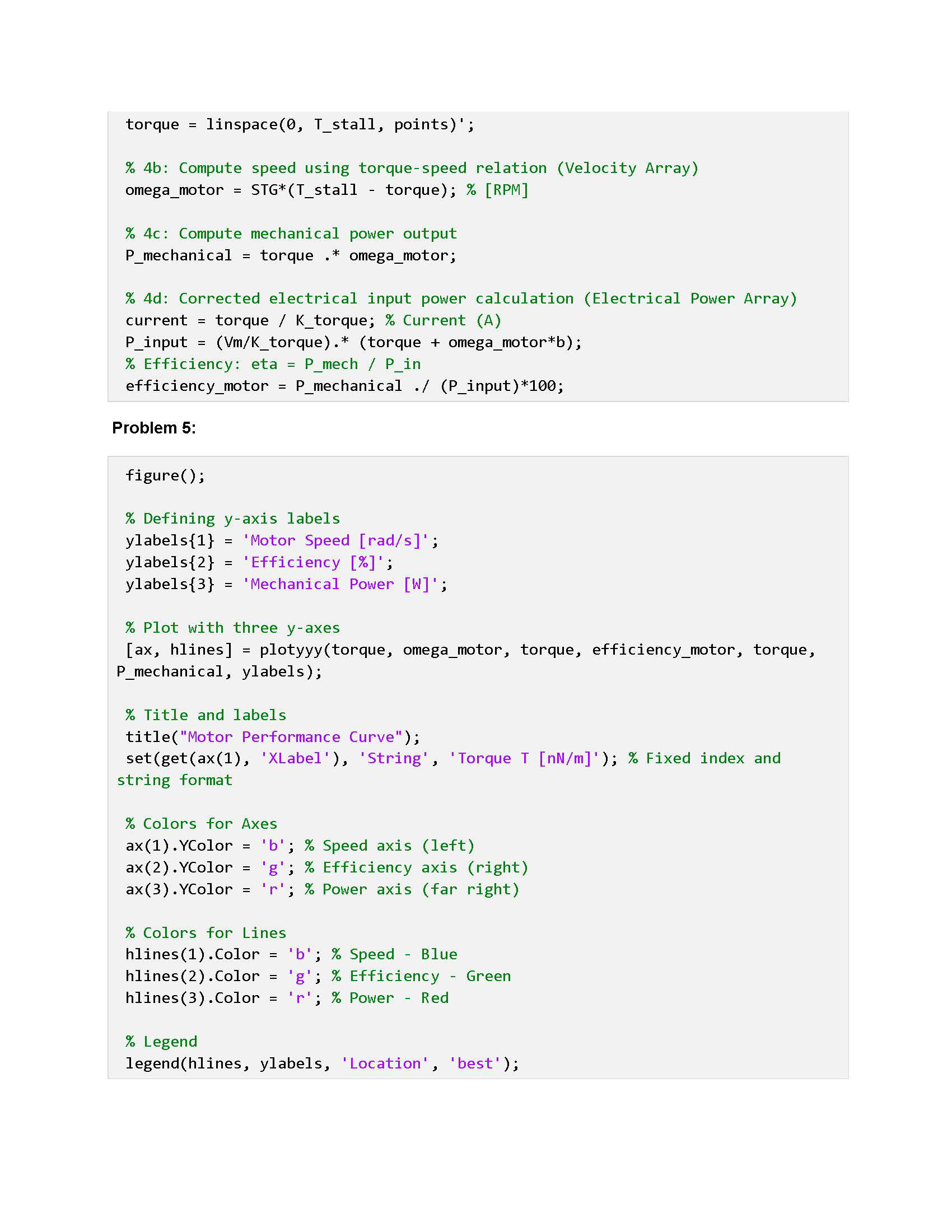
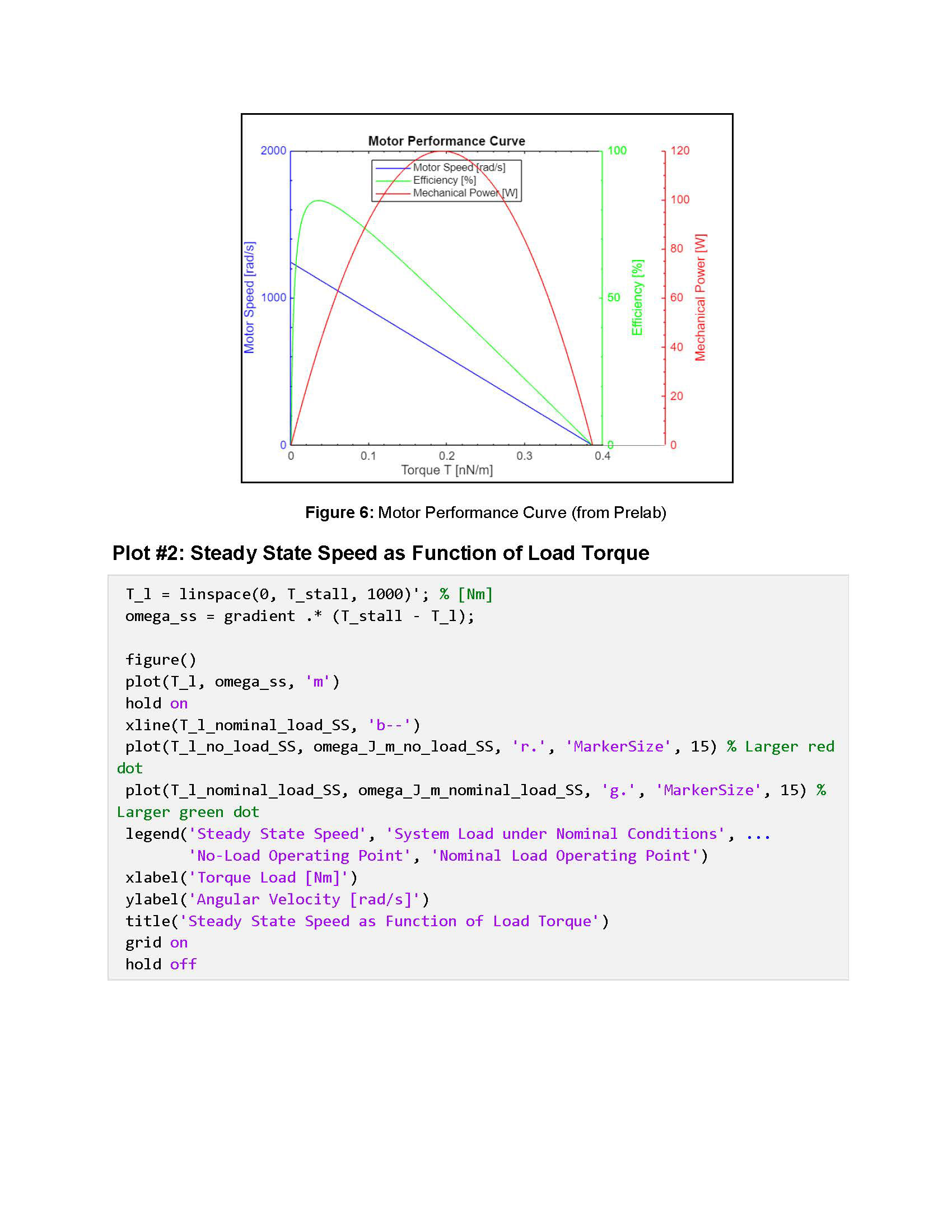
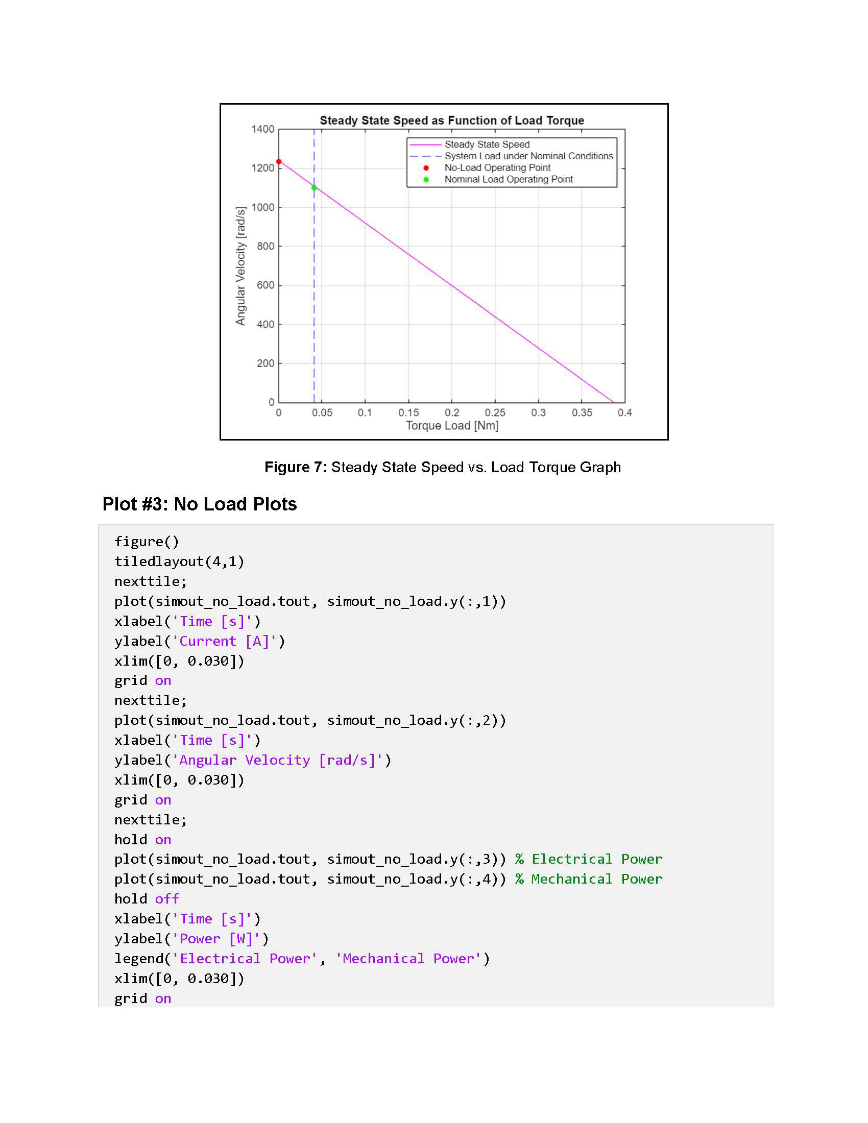
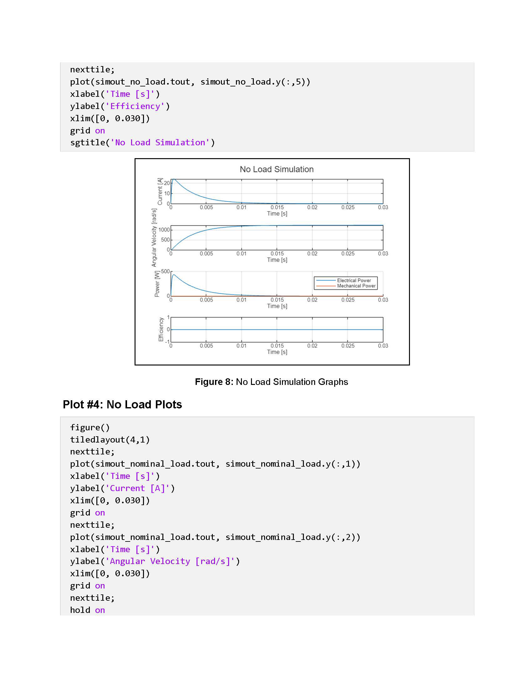
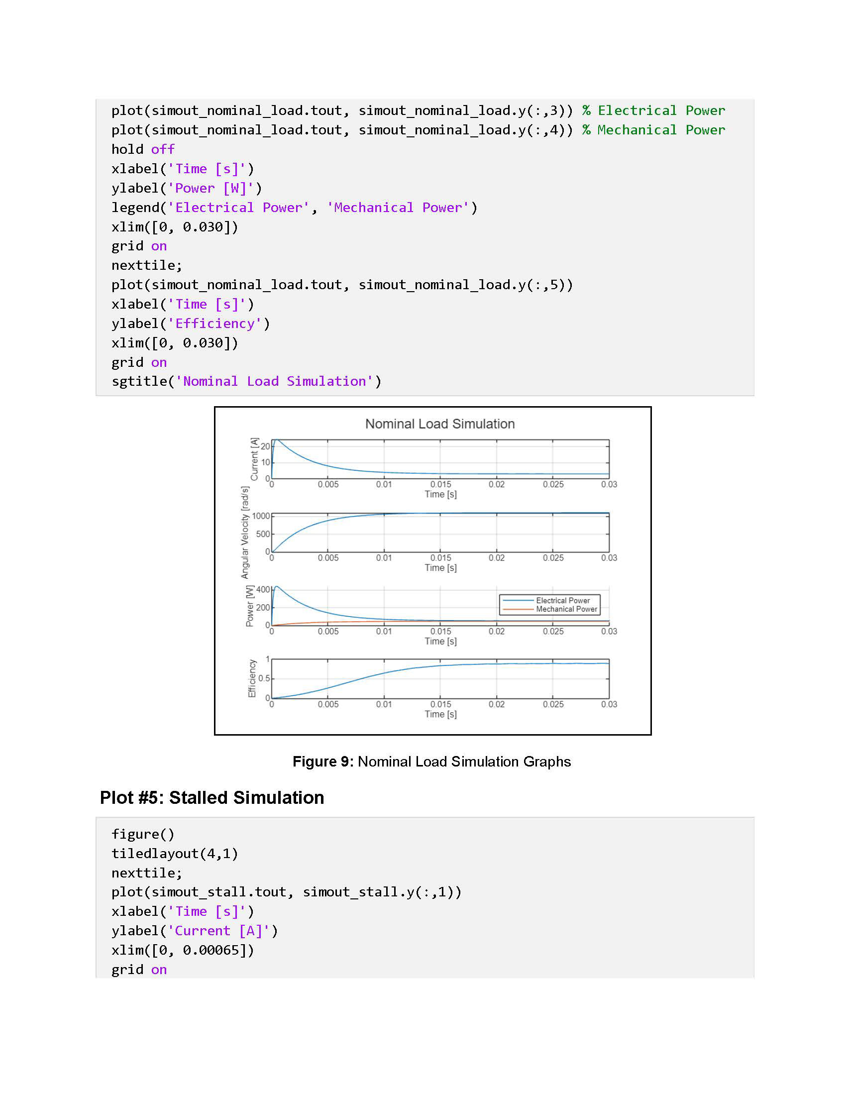
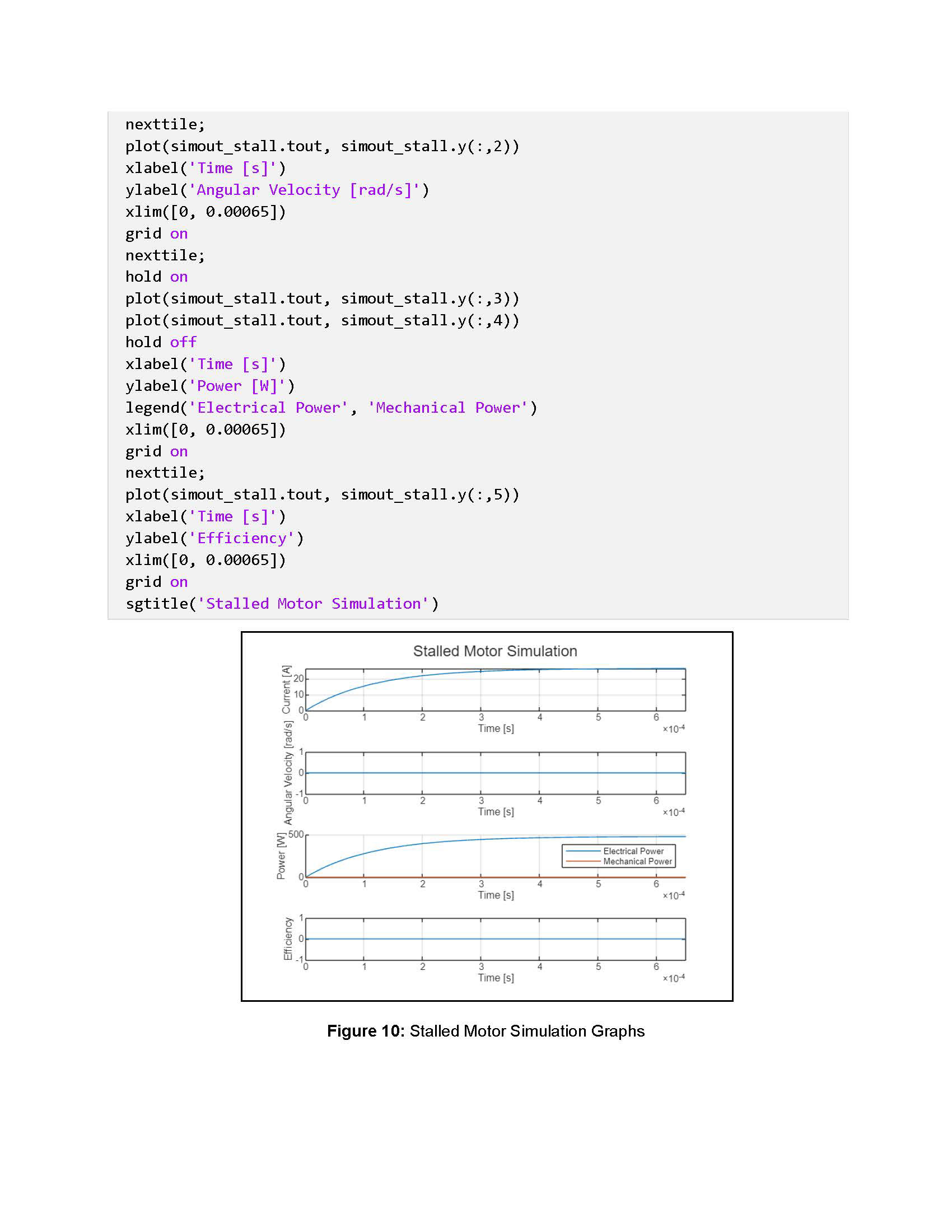
In this lab, I investigated the static and dynamic behavior of a Maxon DCX22L DC motor, analyzing its speed-torque characteristics, electromechanical response, and thermal performance under different conditions. Using hand calculations and MATLAB simulations, I evaluated key parameters such as stall current, torque constant, and efficiency. Additionally, I developed Simulink models to simulate the motor’s steady-state and transient response under nominal load, no-load, and stall conditions. The results provided insights into the motor's thermal limitations, efficiency trends, and operating behavior, reinforcing key principles of electromechanical energy conversion and thermal management in DC motors.
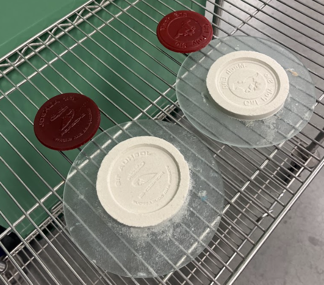
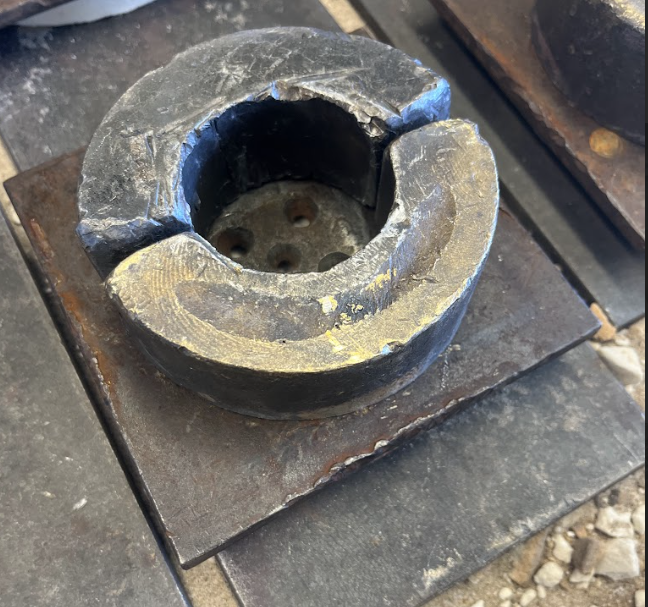
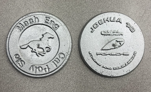
The above two and left images are from my IME-141 Metal Casting class. We used a Lost Wax process to create a mold (red), which was then casted with Aluminum to create two custom medallion designs.