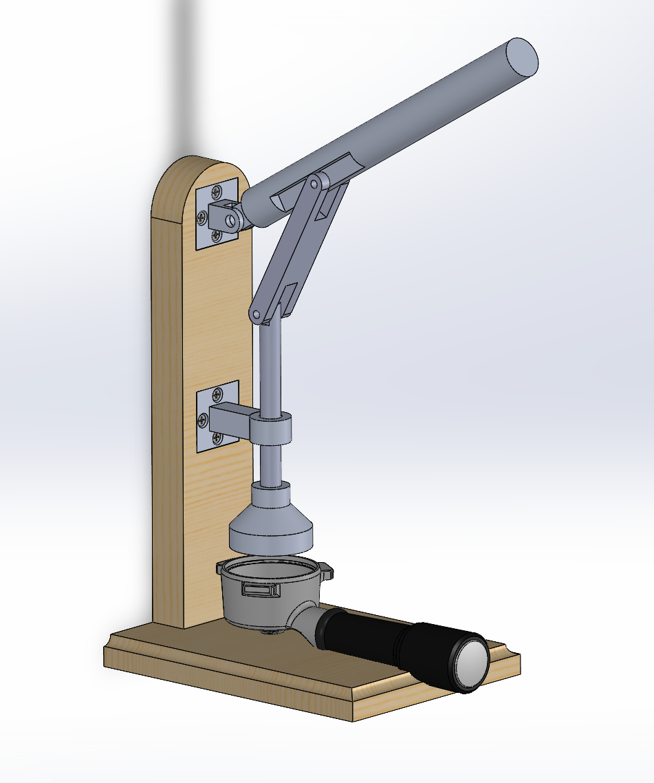
This project was born out of my passion for coffee—not just the drink itself, but the craft behind it. I’ve always been drawn to processes that transform raw materials into refined outcomes, and espresso preparation exemplifies that. As a mechanical engineering student, I naturally approach these systems with a mindset focused on precision, repeatability, and continuous improvement.
When I began pulling espresso shots on my parents’ home machine, I quickly became fascinated by the technical subtleties—grind size, extraction pressure, tamping angle—all of which influence the final result. That curiosity led me to design and build a mechanical espresso tamper. My goal was to create a tool that feels robust in hand, eliminates variability, and delivers consistent performance with every use.
Original Brainstorming/Idea Framework:
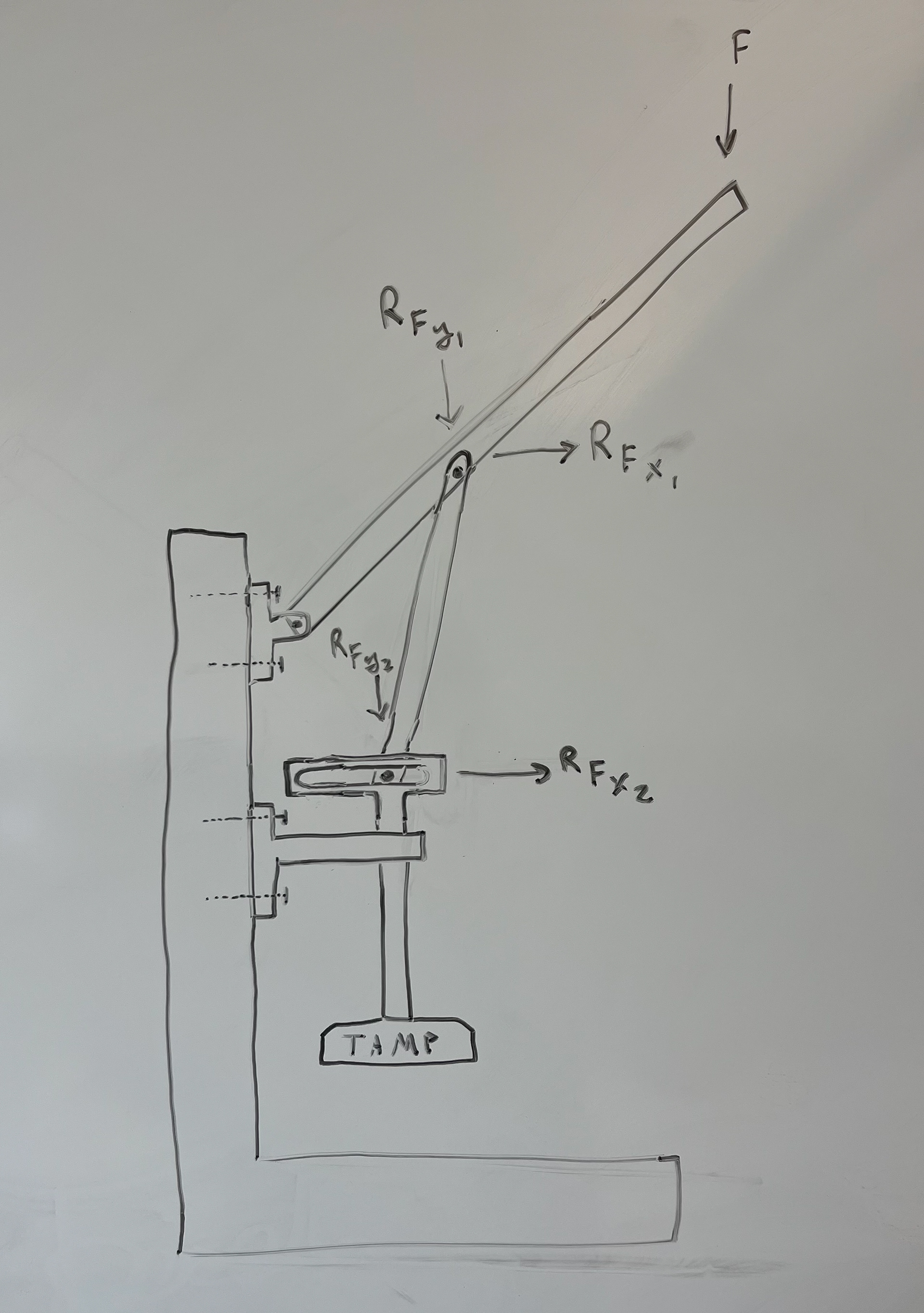
It all started on the whiteboard. I was messing around with ideas and sketched out this linkage. I wanted a design that could take a simple force from my hand and convert it into a clean vertical tamping force. I played with angles... pivot points... tried to balance mechanical advantage with compact size. The goal was to make it feel solid without needing a ton of force. This was the first concept that made sense. From here I could start thinking about materials and how to build the joints. But it had to start with something I could see and change fast. The whiteboard helped me figure it out.
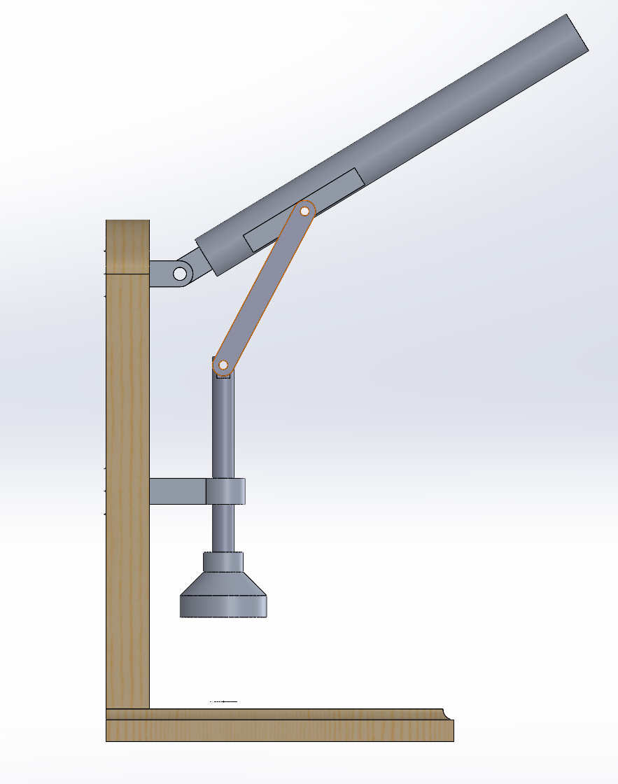
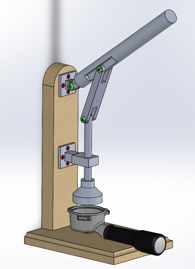
Once the whiteboard sketch looked right, I moved into CAD. I opened up SolidWorks and started with the frame and lever geometry. I kept the same layout from the board... just needed real dimensions now. The pivots became mates. The wood base and vertical support were modeled first so I had something to build around. Then I added the arms, defined lengths, and adjusted the linkage to match the motion I wanted. I tested the tamping stroke and made sure it moved straight down without binding. Most of the work was in tweaking arm lengths and pin locations until the travel felt right. Once that was done, I added more detail... handle profile, tamp shape, and hardware. From here I could think about materials and fabrication. CAD helped me turn the sketch into something buildable.
Choosing Hardware/Fastening:
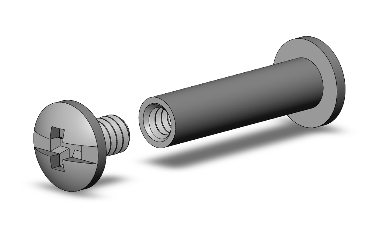
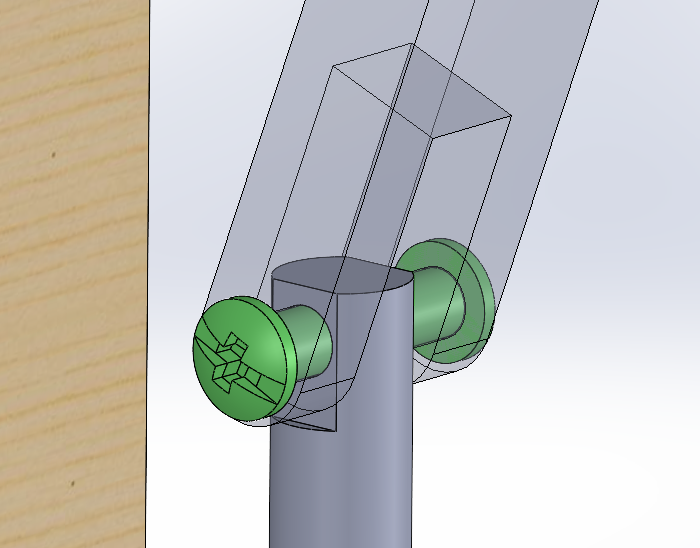
To enable pivoting motion in my 6061 aluminum assembly, I selected components from McMaster-Carr’s binding barrel fastener series. Specifically, I used:
• 99637A306 – a 1" steel binding barrel and screw set
• 99637A313 – a 1-1/2" steel binding barrel only
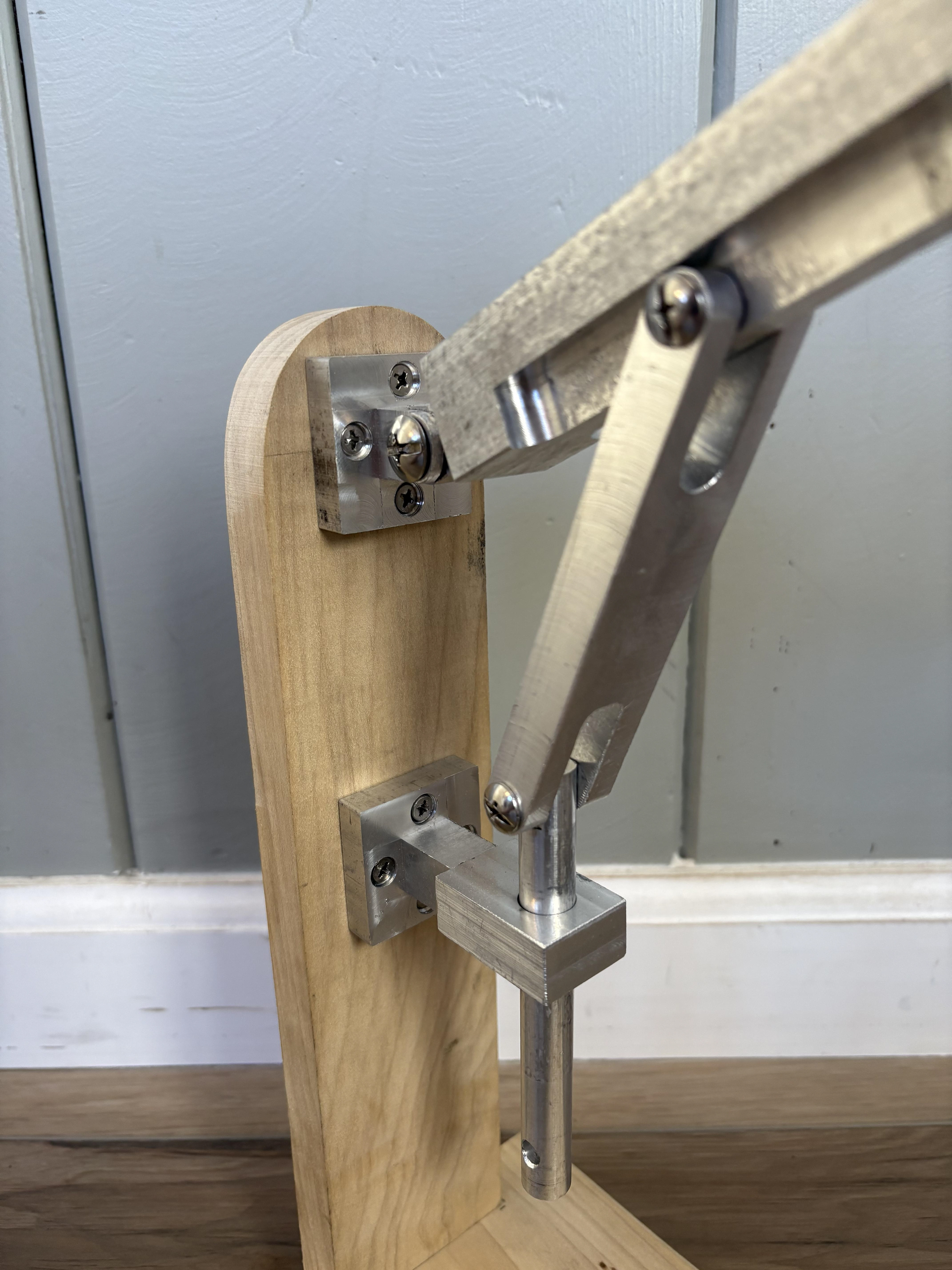
These fasteners are designed with a smooth outer barrel, allowing me to use them as both a mechanical pivot and a structural fastener. While originally intended for wood, their mechanical form and material properties made them well-suited for use in aluminum components, where the steel barrel serves as a durable low-friction bearing surface.
In locations requiring longer reach through thicker material or more clearance between components, I used the 1-1/2" barrel (99637A313) with a separately selected screw to maintain compatibility and clamping strength. The design enabled a simple and compact pivot joint that didn't require separate bushings or bearings, with the steel providing better wear resistance than aluminum-on-aluminum contact.
This setup proved to be an efficient, low-profile, and cost-effective solution for joints requiring rotation, without compromising the structural integrity of the assembly.

Once the CAD was dialed in, I started looking for material. I scrounged around the shop and got help from a few professors at Cal Poly to find scrap stock that would work for the final build. While that was coming together, I didn’t want to wait, so I fired up my Ender 3 at home and started printing a prototype. It wasn’t about strength yet—it was about motion. I wanted to test the linkage, see if the arms moved how I expected, and check clearances. The print let me find issues early without wasting metal.
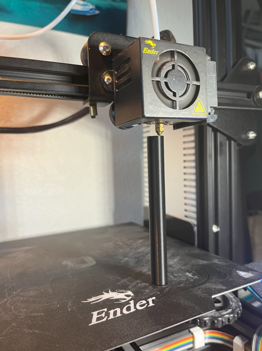
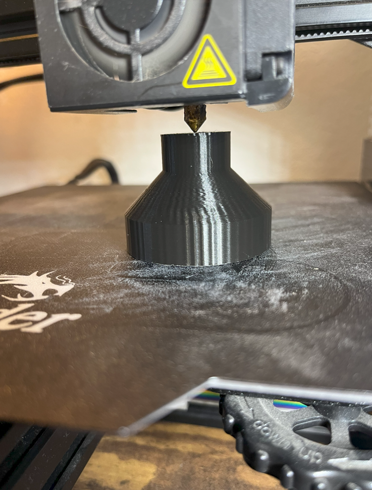
Above: 3D Printing portions of the prototype.
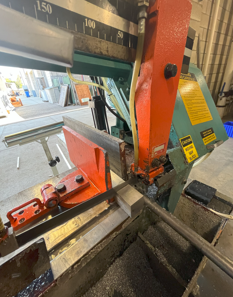
Below: Cutting my nominal stock to size. All metal used was 6061-T6 Aluminum. Bar stock or round stock.
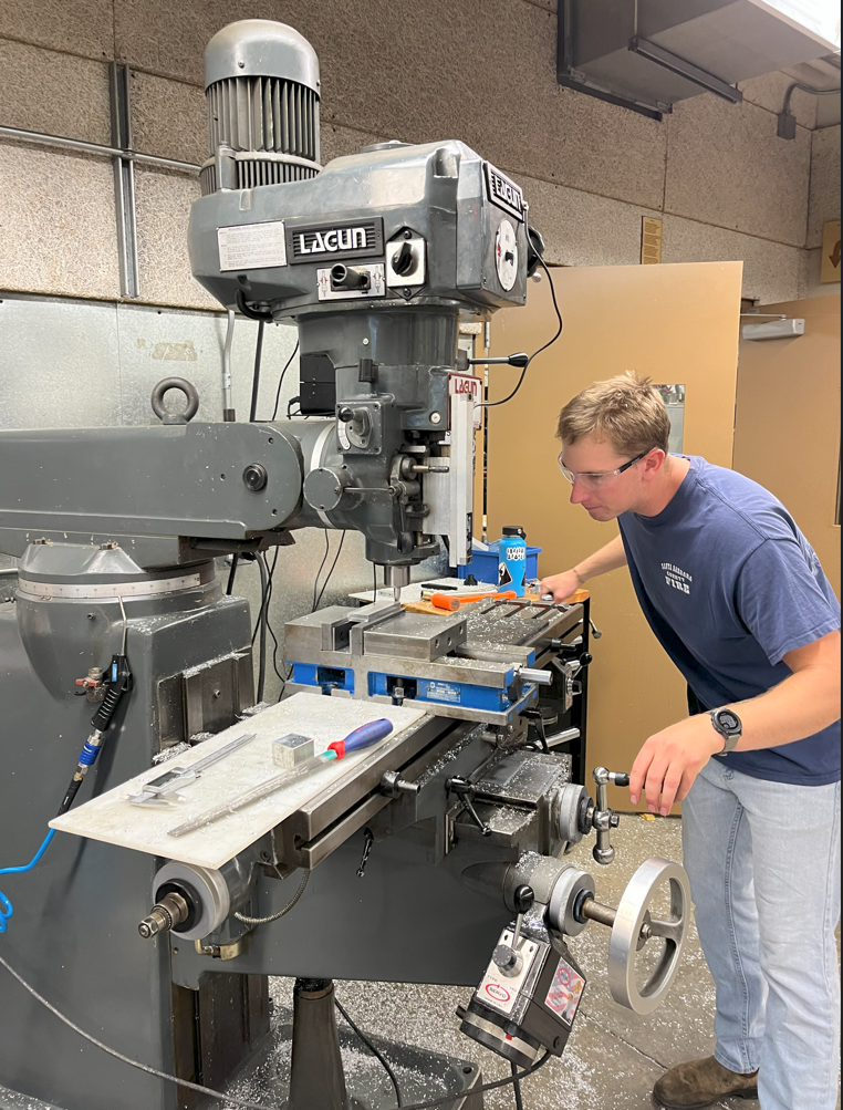
Below: Using a manual mill to manually machine my components to size following my engineering part drawings.
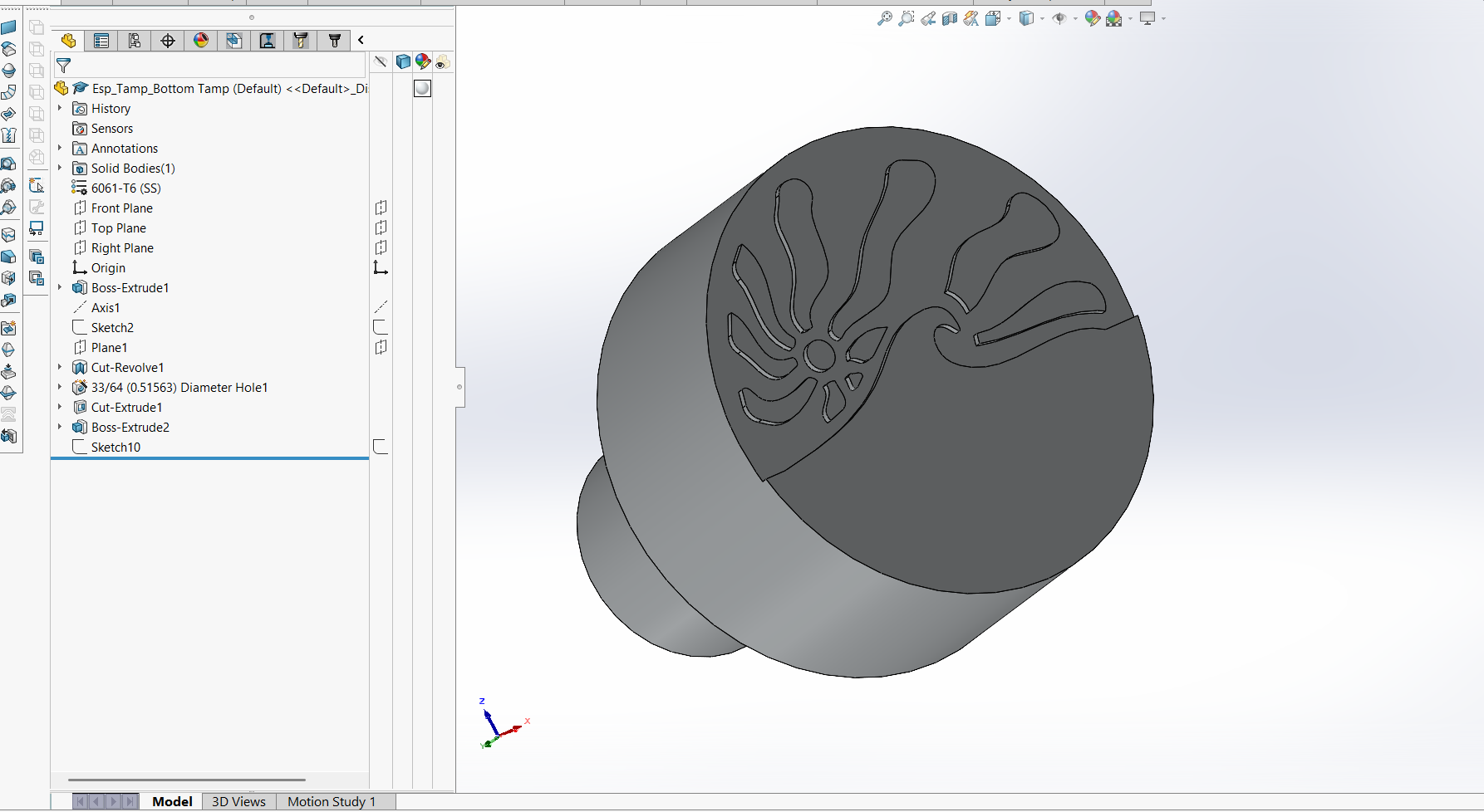
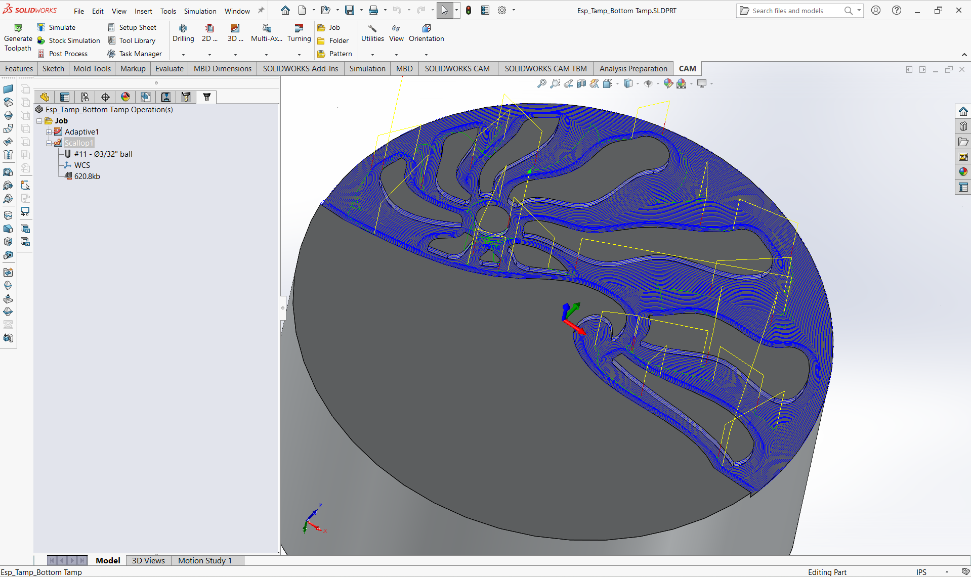
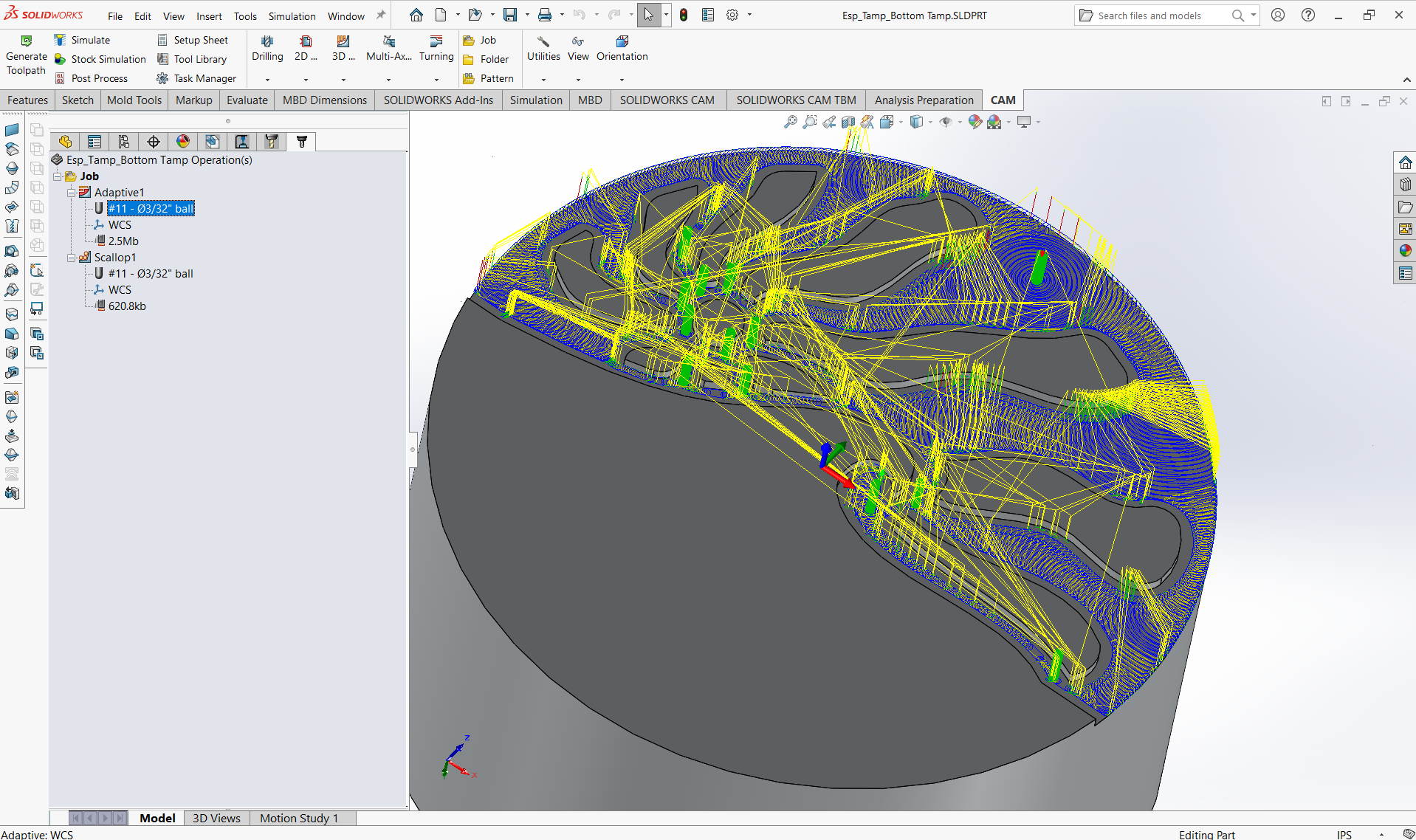
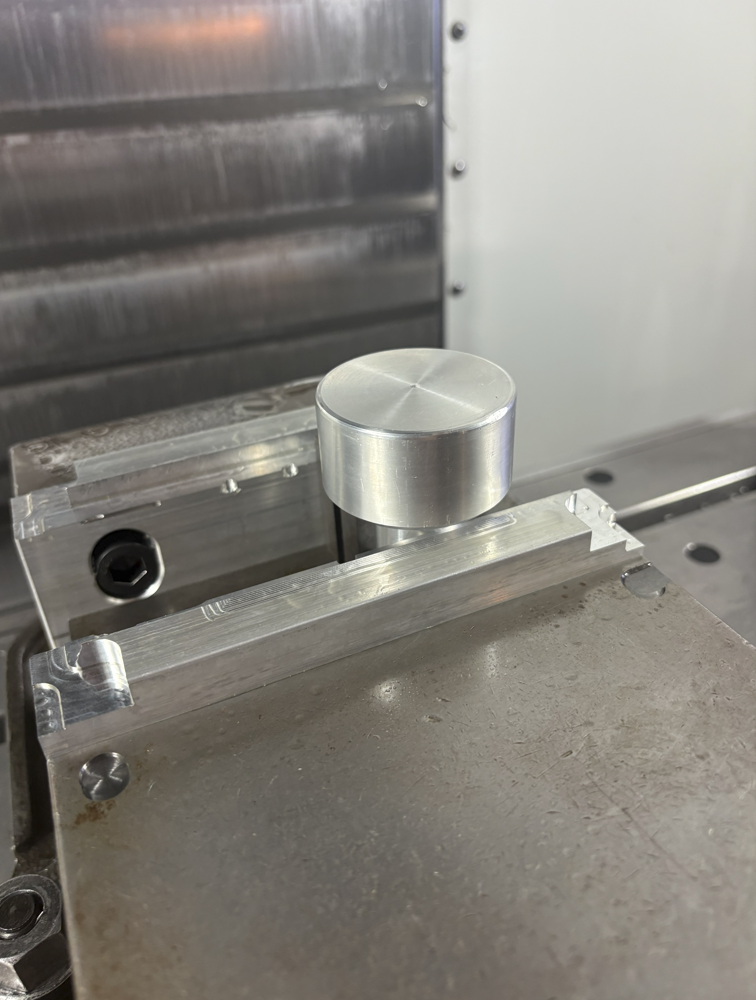
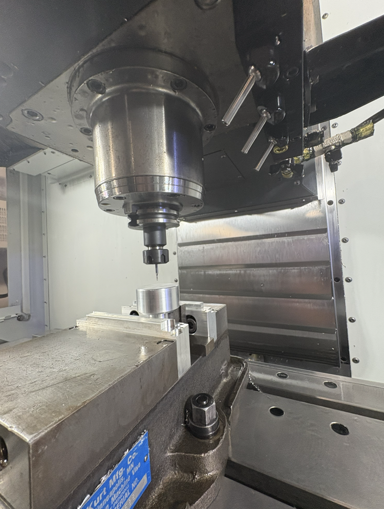
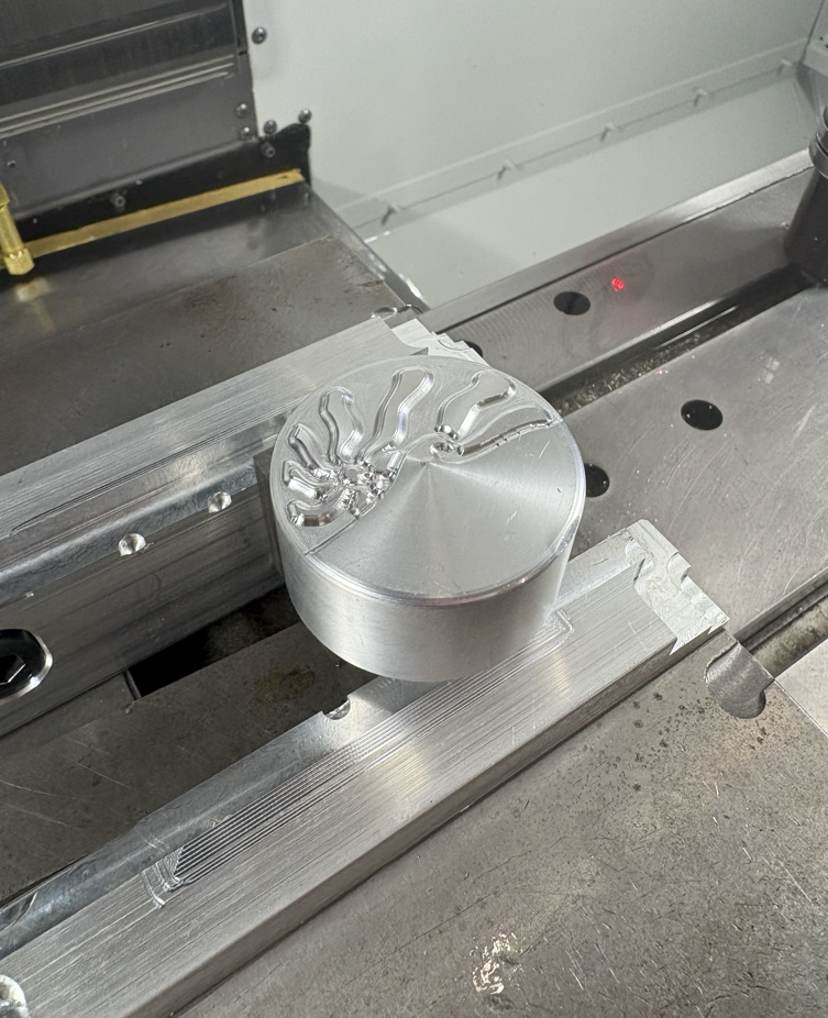
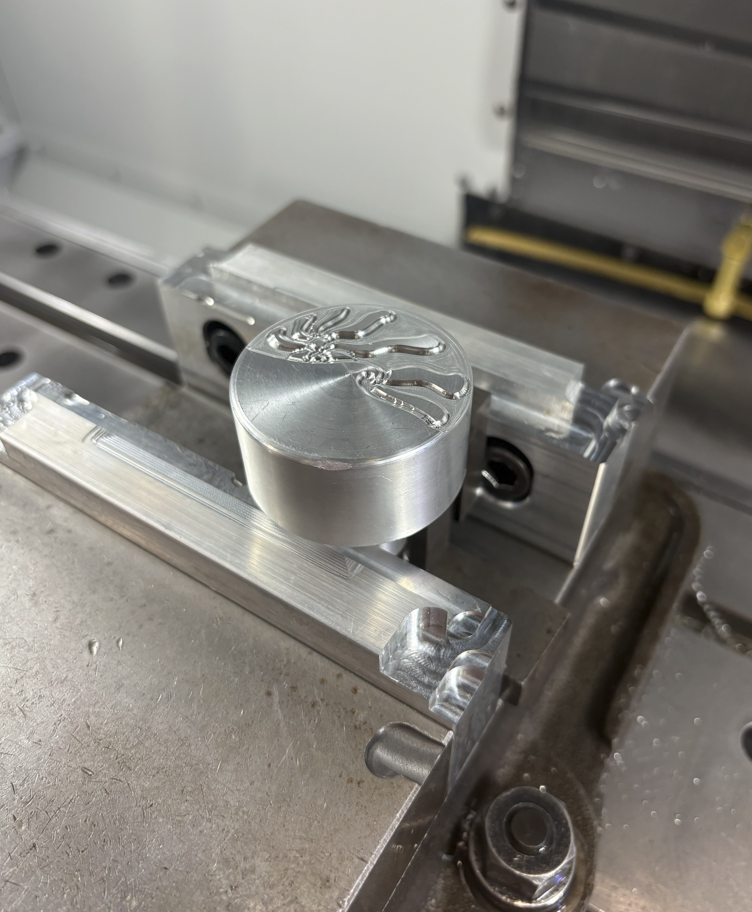
After machining the components of the linkage, I wanted the coffee tamper to do more than just function, it should leave a distinct signature each time it was used. I set out to design a pattern that reflected motion and energy. The final concept combined stylized waves, a rising sun, and flowing water lines to create a dynamic surface impression. I modeled the design in CAD, refined the geometry for toolpath optimization, and then used a HAAS VF-2 CNC mill to precisely machine the pattern into the base of the tamper. The result was a functional tool that transformed a routine motion into a small act of artistry, producing a unique imprint with every tamp.
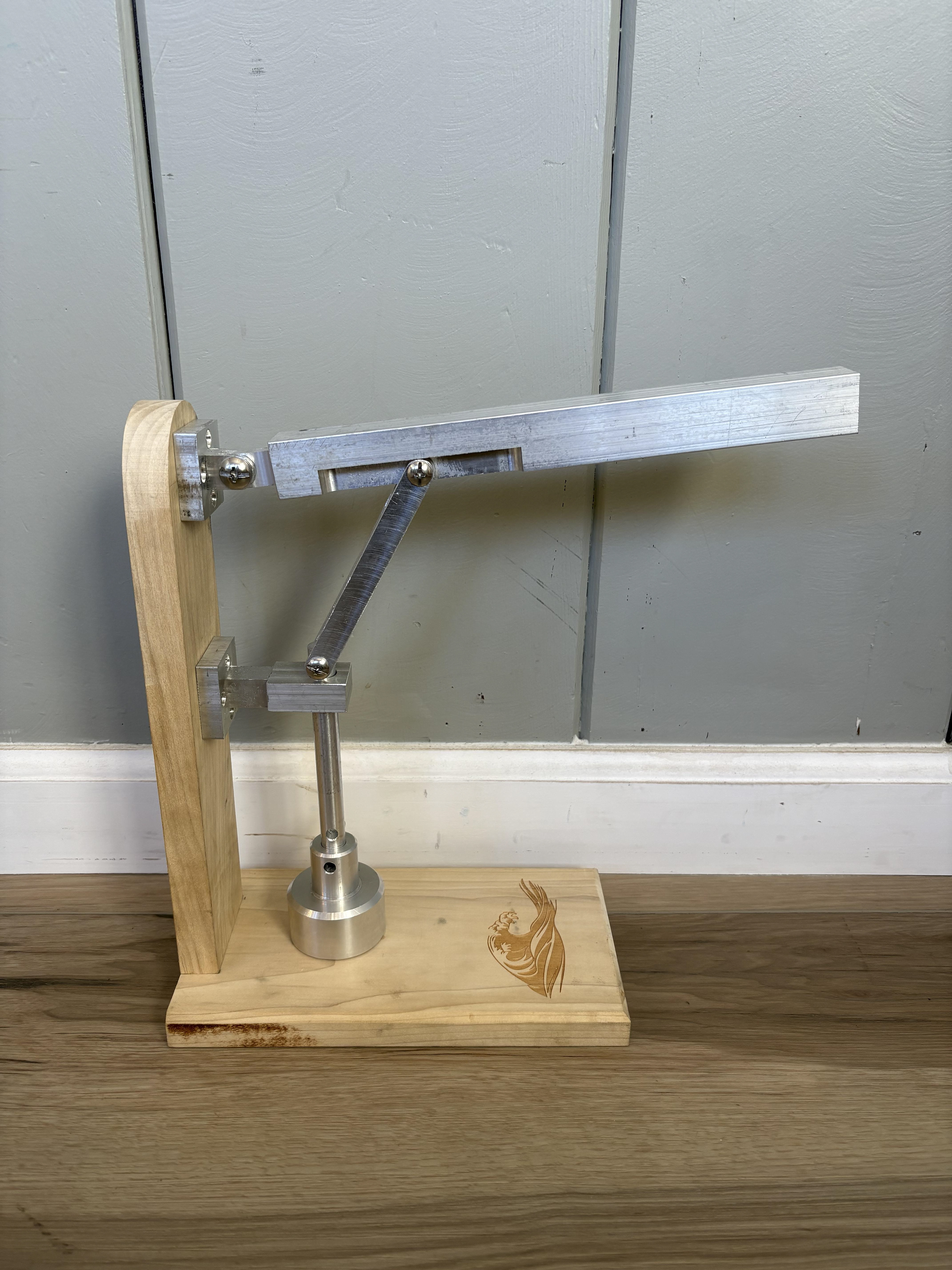
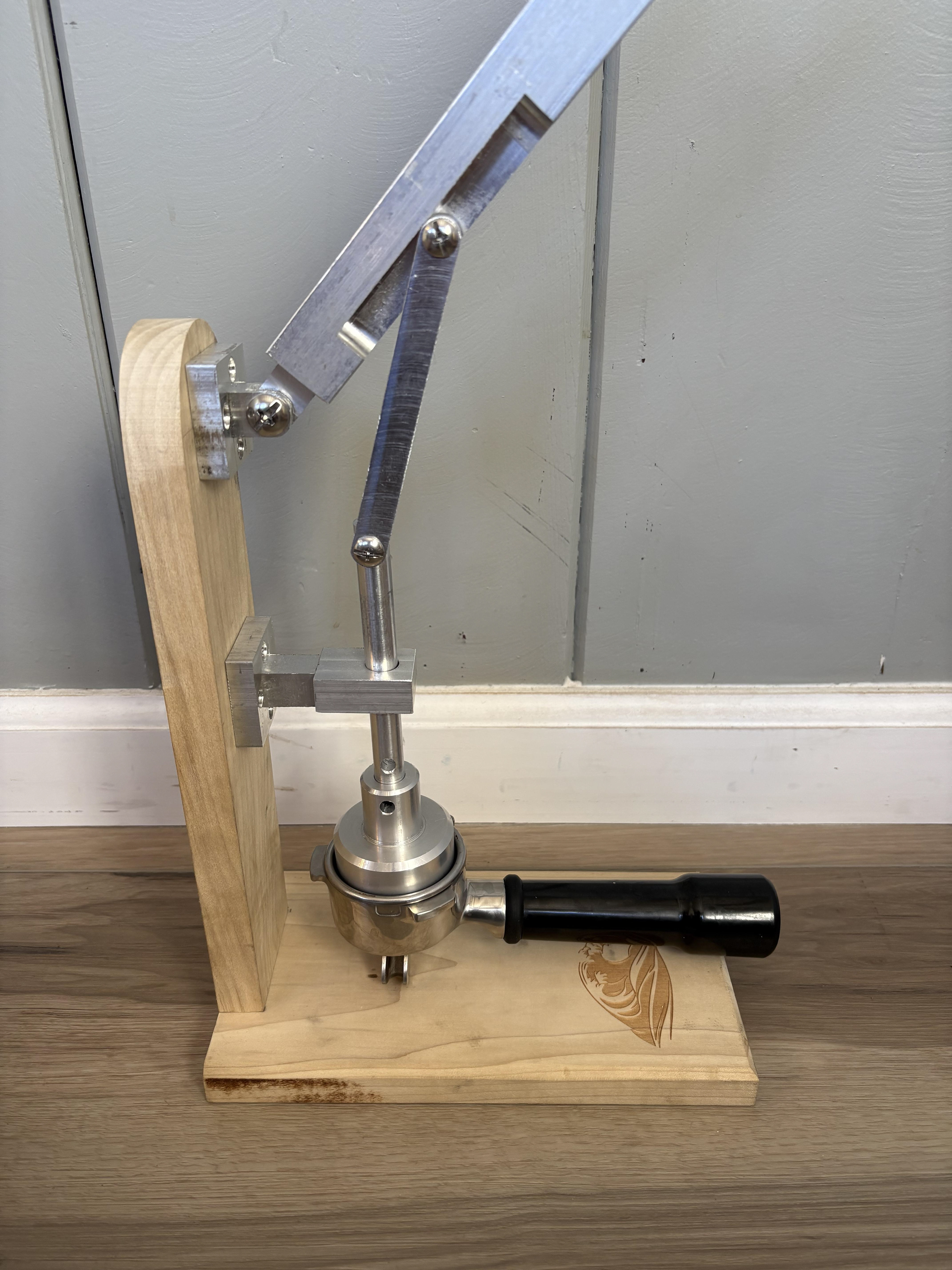
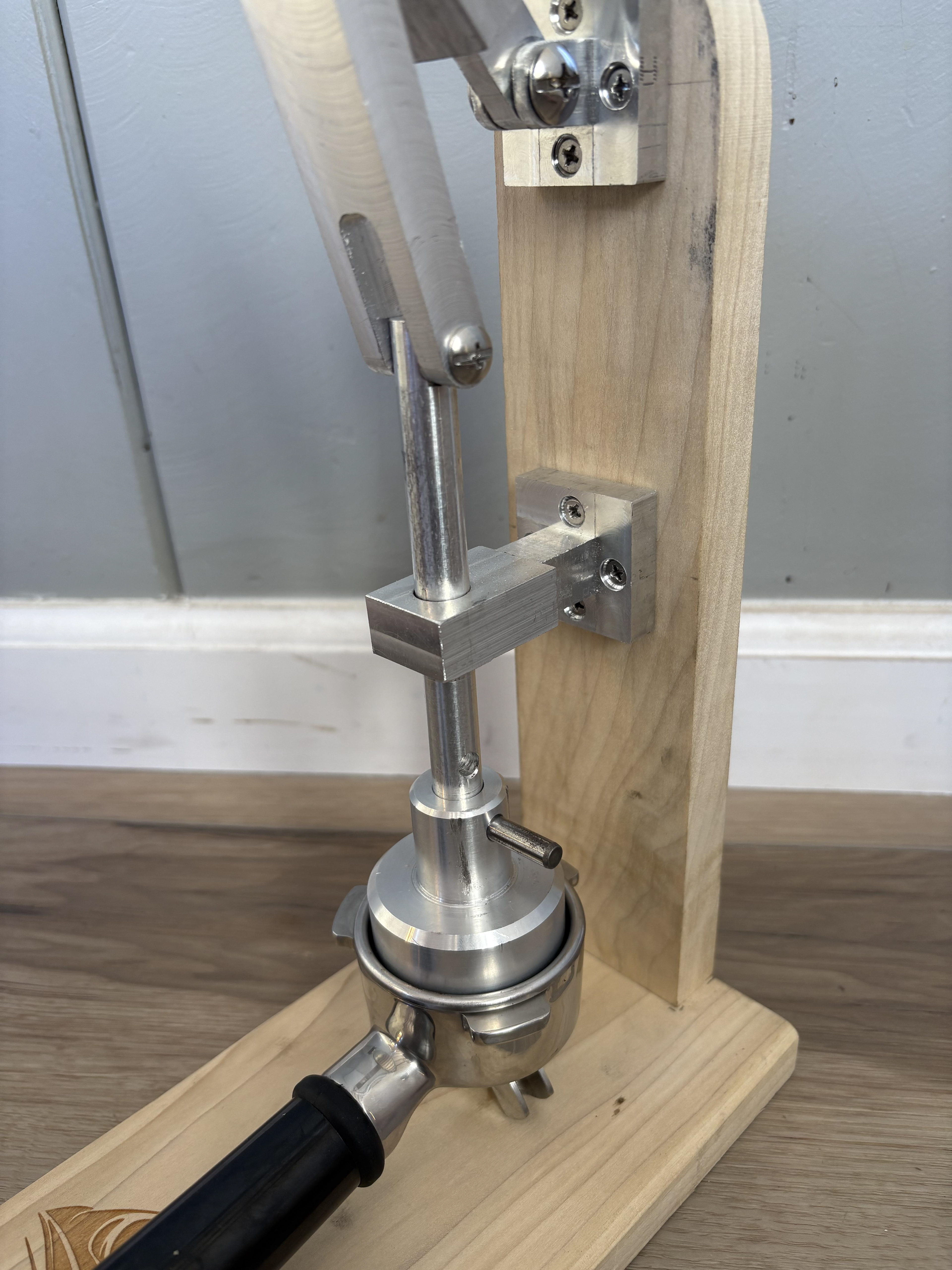
Final Assembly
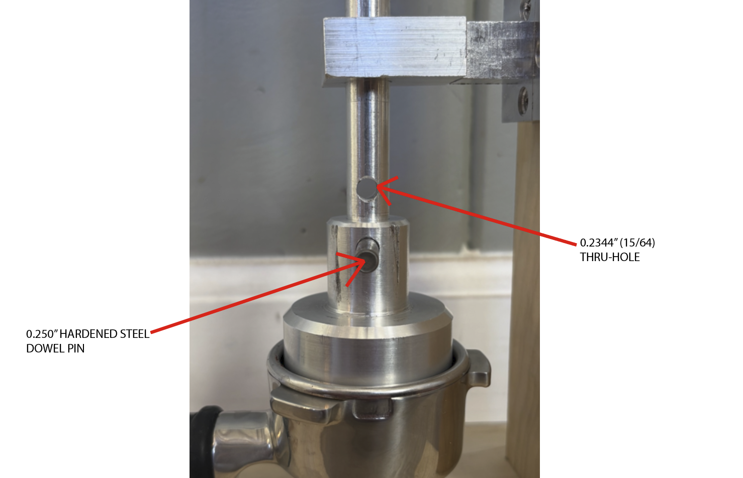
Error Description:
In the linkage assembly for my espresso tamp project, I intended to create a press-fit joint using a hardened steel dowel pin to lock two aluminum components together. The dowel pin was designed to be slightly larger than the through-hole, creating an interference fit that would permanently secure the parts. However, I underestimated the required precision of the fit and drilled the holes undersized on both components. When I attempted to press-fit the dowel pin, the interference was excessive, causing the pin to seize in one component before passing through the second. As a result, the assembly could not be completed, and one part was effectively scrapped.
Root Cause:
The error resulted from skipping the reaming process and relying solely on drilling to achieve the final dimension. Drilling alone cannot reliably produce the tolerance necessary for controlled interference fits, especially between dissimilar materials like aluminum (6061-T6) and hardened steel.
Technical Correction:
For a steel dowel pin in an aluminum hole, a typical interference range is 0.0003"–0.0010" per inch of diameter.
For example, with a ¼" (0.250") dowel pin, the hole diameter should be between 0.2490" and 0.2497". This provides a firm press fit without risk of galling or seizure. The correct approach would have been to drill undersize, then ream to the target fit tolerance and verify using gauge pins before assembly.