**Co-Collaborators on this project: Luke Silver, Jake Weiser, and Gabe Junge (California Polytechnic State University, San Luis Obispo). See their LinkedIn profiles below.
For the full downloadable Final Design Report and intermediate design reports, view here from Cal Poly's Digital Commons website:
Project Scope:
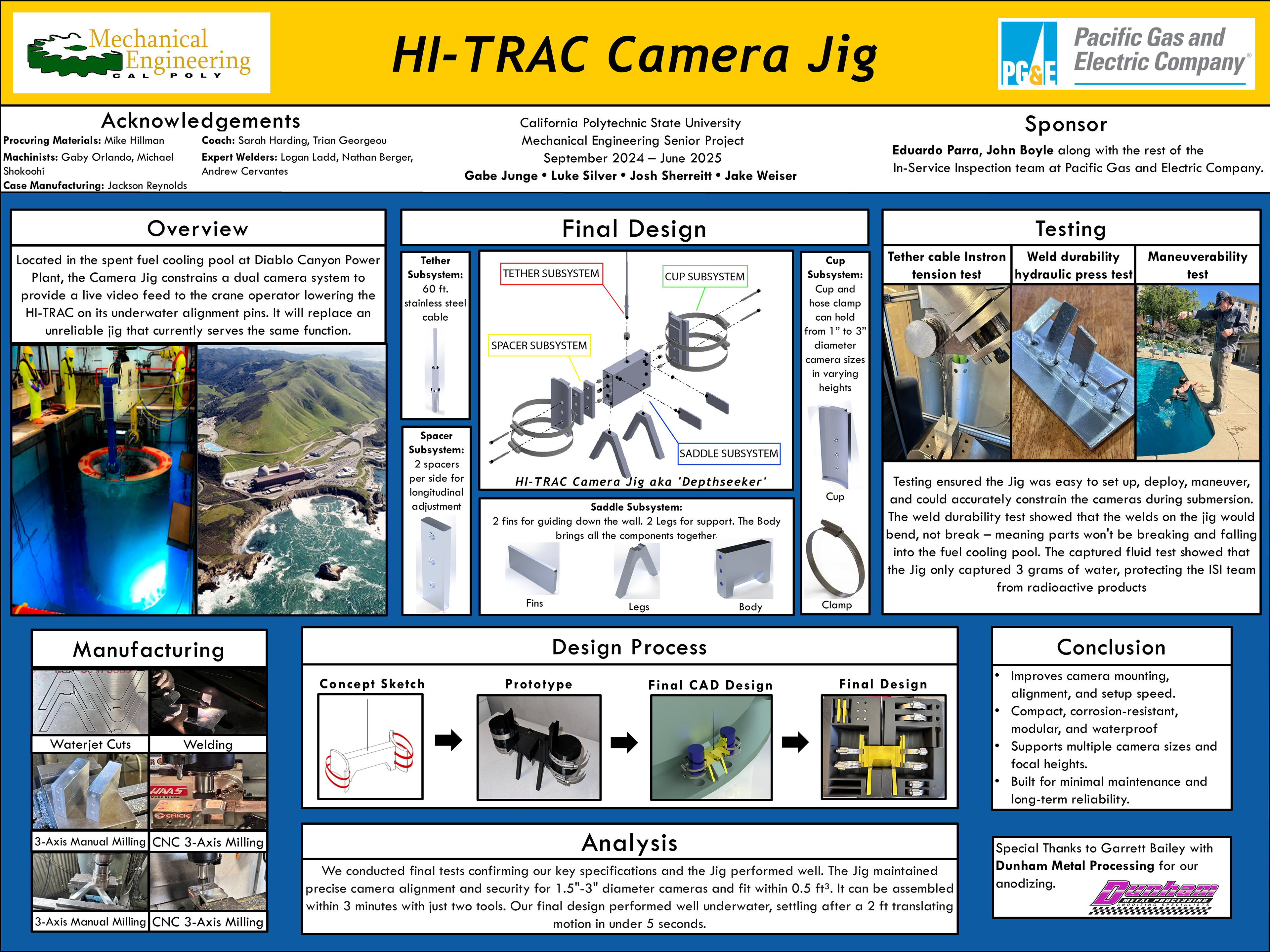
The HI-TRAC Camera Jig project was developed in collaboration with Pacific Gas & Electric (PG&E) for use at the Diablo Canyon Power Plant, located here on the Central Coast of California. Our goal was to redesign a critical camera mounting system used to assist in the underwater alignment of spent nuclear fuel transport vessels, known as HI-TRACs. The existing setup used zip-tied cameras and was prone to misalignment, slow setup, and potential mechanical failure.
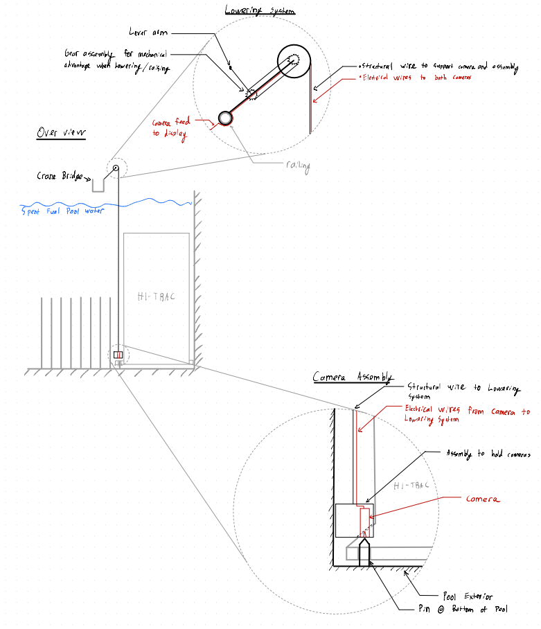
To solve the issue we were presented with, our team devised a design plan (following numerous brainstorming sessions) including a modular, corrosion-resistant camera jig with adjustable mounts for varying camera sizes, a stainless steel tether for safe deployment and retrieval, and a CNC-machined aluminum frame that ensures stability and alignment during use in the spent fuel pool at Diablo Canyon.
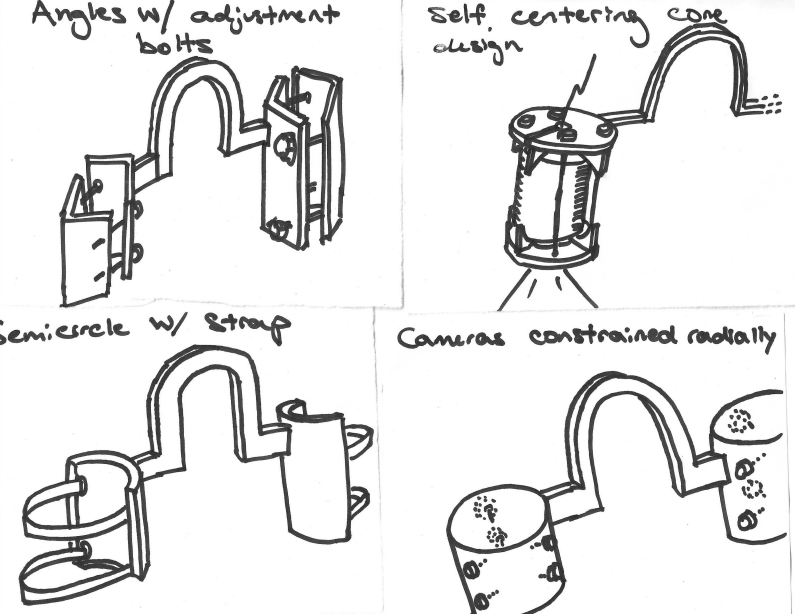
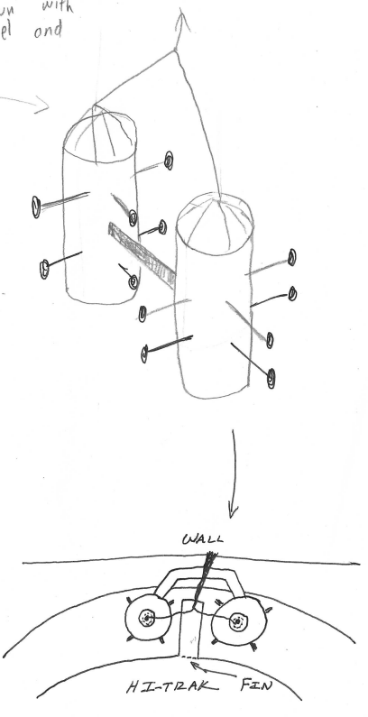
Ideation/Brainstorming:
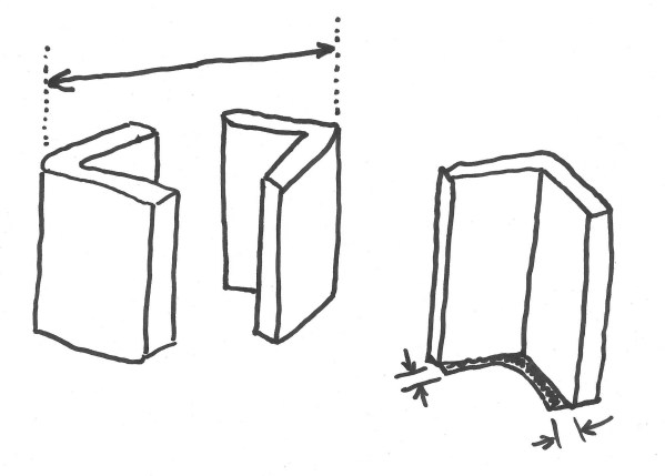
Before jumping into CAD, our team held several structured brainstorming sessions to explore a wide range of camera jig concepts. We sketched out early ideas that prioritized stability, adjustability, and underwater visibility. These concepts included angled mounting arms with adjustment bolts, self-centering cones, semicircular cradles with straps, and radial camera constraints. Each idea was evaluated for mechanical feasibility, ease of manufacturing, and compatibility with different camera sizes. These hand-drawn concepts helped us compare design tradeoffs visually and guided our transition into digital modeling.

CAD Designing:
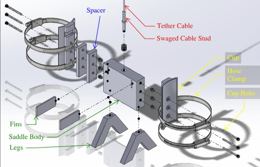
We began with CAD modeling in SolidWorks, focusing on how each subsystem—saddle, spacer, cup, and tether (shown below)—would interact with the geometry of the HI-TRAC and the constraints of the fuel pool. We iterated on several designs to optimize alignment accuracy, ease of assembly, and adaptability to different camera sizes. These digital models were crucial not only for visualizing the final product but also for verifying fit, manufacturability, and space constraints early in the process.
Our assembly consists of:
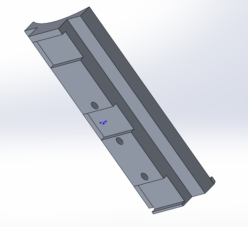
1. Saddle Body
Purpose: Acts as the structural backbone of the jig. It supports and aligns all other subsystems and straddles the HI-TRAC fin for proper positioning over the alignment pins.
Purpose: Acts as the structural backbone of the jig. It supports and aligns all other subsystems and straddles the HI-TRAC fin for proper positioning over the alignment pins.
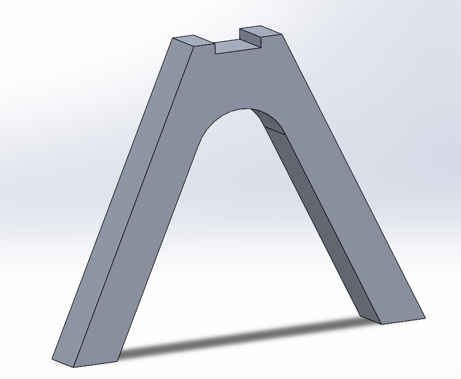
2. Saddle Legs (x2)
Purpose: Provides vertical elevation from the HI-TRAC flange and stabilizes the jig on the fin. Welded to the saddle body.
Purpose: Provides vertical elevation from the HI-TRAC flange and stabilizes the jig on the fin. Welded to the saddle body.
3. Saddle Fins (x2)
Purpose: Extend outward to help guide the jig during deployment and maintain lateral stability against the pool wall.
Purpose: Extend outward to help guide the jig during deployment and maintain lateral stability against the pool wall.
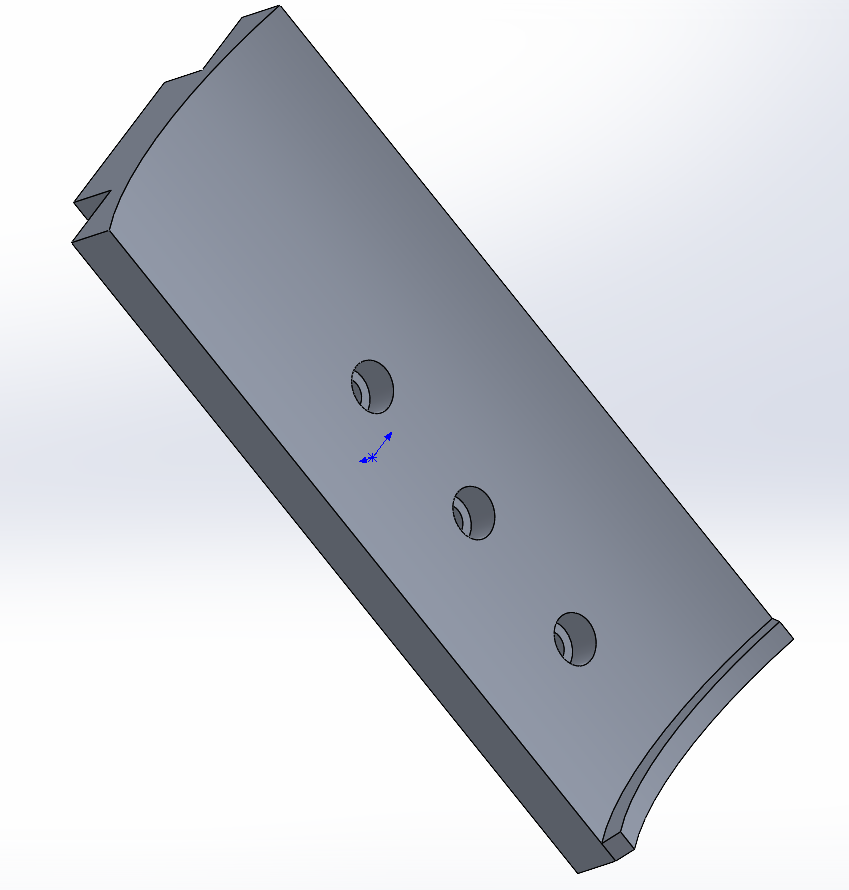
4. Camera Cups (x2)
Purpose: Holds the cameras securely in place. Designed with hose clamp slots to accommodate different camera diameters.
Purpose: Holds the cameras securely in place. Designed with hose clamp slots to accommodate different camera diameters.
5. Hose Clamps (x2 per cup)
Purpose: Wrap around each camera to clamp it firmly into the cup. Easily adjustable for various sizes.
Purpose: Wrap around each camera to clamp it firmly into the cup. Easily adjustable for various sizes.
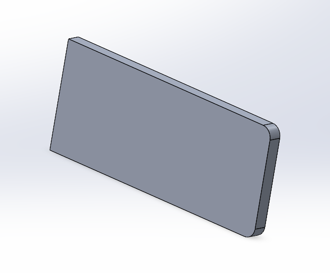
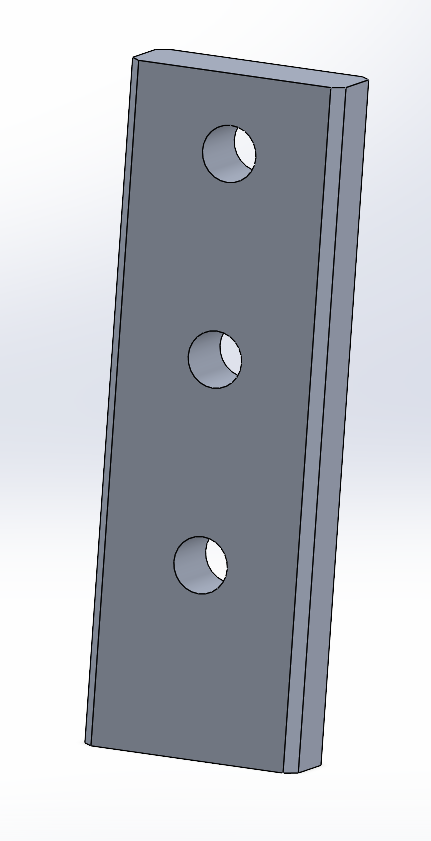
6. Spacer Blocks (up to 2 per side)
Purpose: Allow for adjustable center-to-center spacing and vertical alignment of cameras, compensating for camera size and focal distance.
Purpose: Allow for adjustable center-to-center spacing and vertical alignment of cameras, compensating for camera size and focal distance.
7. Cup Bolts (3 per cup)
Purpose: Bolt the camera cups (and spacers) into the saddle body. Allow height adjustment via alternate mounting holes.
Purpose: Bolt the camera cups (and spacers) into the saddle body. Allow height adjustment via alternate mounting holes.
8. Steel Threaded Inserts (press-fit)
Purpose: Provide strong, corrosion-resistant threads in the aluminum saddle body for mounting bolts and tether attachment.
Purpose: Provide strong, corrosion-resistant threads in the aluminum saddle body for mounting bolts and tether attachment.
9. Tether Cable (60 ft, stainless steel)
Purpose: Main tether used to raise, lower, and retrieve the jig. Strong enough to recover the jig if it becomes stuck.
Purpose: Main tether used to raise, lower, and retrieve the jig. Strong enough to recover the jig if it becomes stuck.
10. Swaged Cable Stud
Purpose: Terminates the tether cable and screws into a threaded insert in the saddle. Designed for durability and tensile strength.
Purpose: Terminates the tether cable and screws into a threaded insert in the saddle. Designed for durability and tensile strength.
11. Cable Tie
Purpose: Used to secure the camera video feed lines to the tether cable, keeping everything organized during deployment.
Purpose: Used to secure the camera video feed lines to the tether cable, keeping everything organized during deployment.

"Saddle"
"Cup"
"FIN" "LEG"
"SPACER"
PROTOTYPING
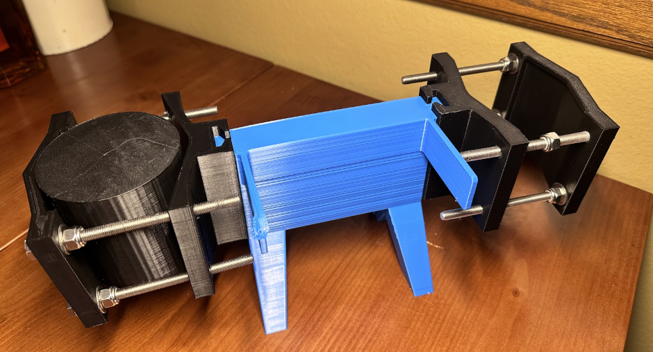
We used 3D printing extensively throughout the prototyping phase to rapidly validate form, fit, and function. For the concept prototype, additive manufacturing allowed us to quickly produce complex geometry that would have been impractical to machine given our timeline and material constraints. This iteration exposed issues with clearance—particularly in the dovetail joint between the saddle and camera cup—which required sanding and manual force to assemble. That experience underscored the importance of tolerancing in multi-part assemblies and influenced our adjustments for future fabrication.
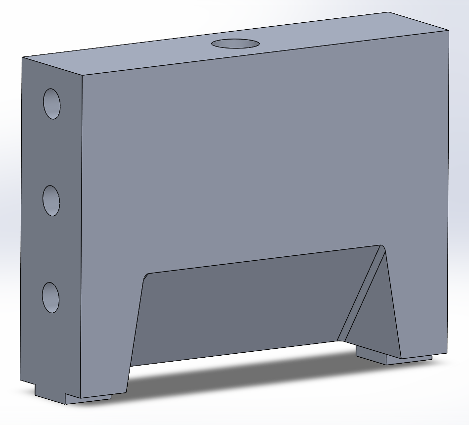
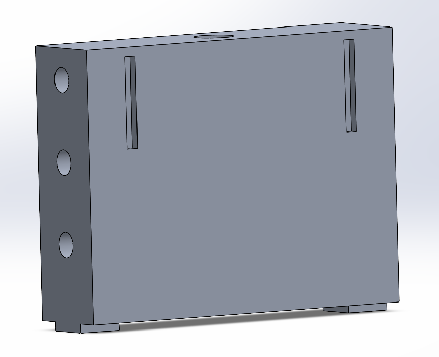
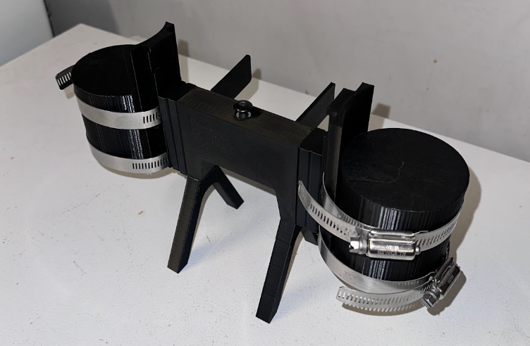
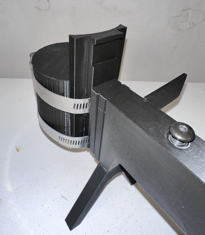
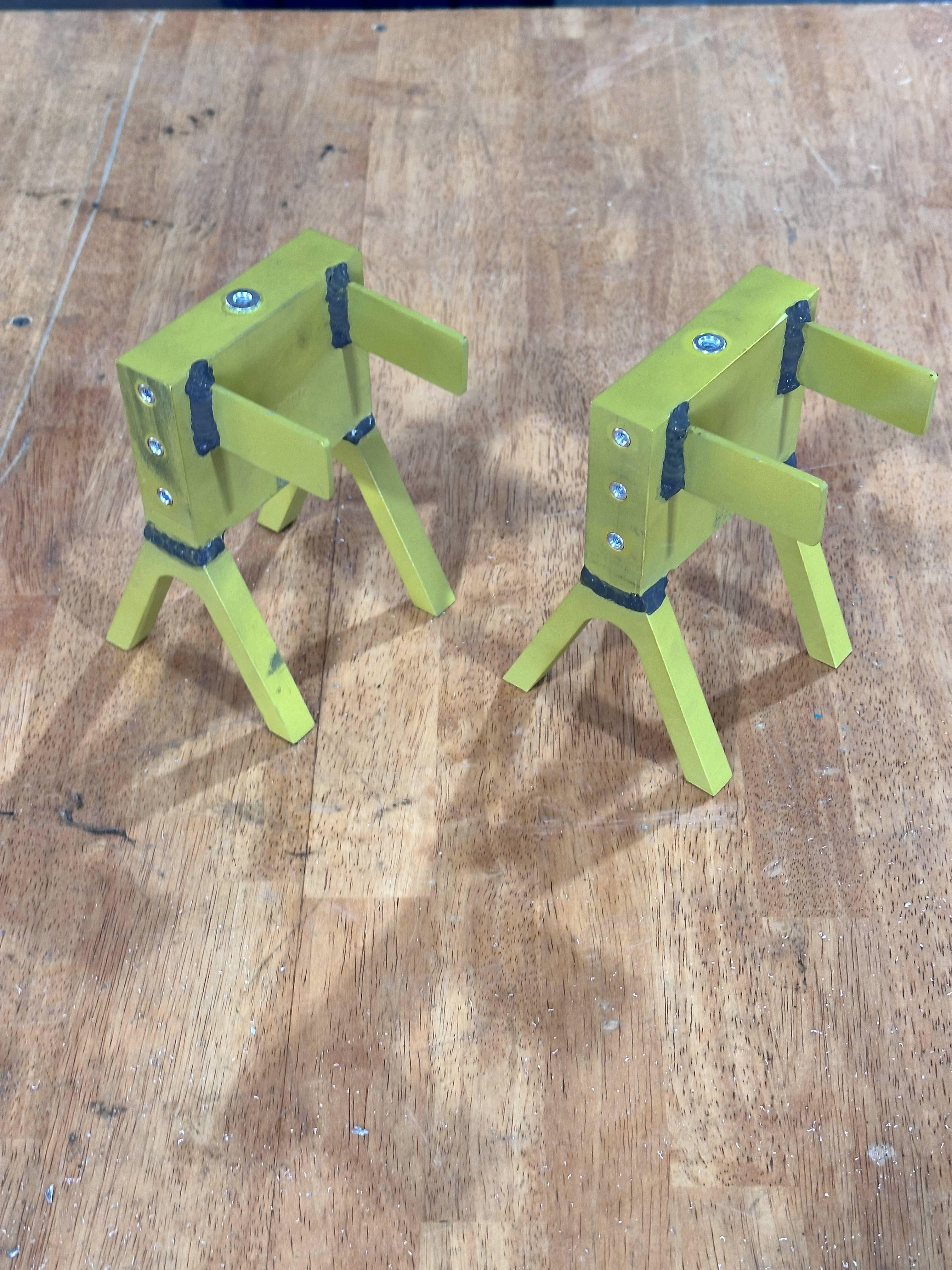
The structural prototype further validated the jig’s mechanical integrity and modular design. By separating the saddle body, legs, and fins, we improved both assembly and future design flexibility. The printed cup confirmed our sizing assumptions, but also revealed the need for increased height to fit larger cameras. It also led to a change in our mounting strategy—replacing bowtie flanges (seen in the image below) with a through-bolt locator design to simplify manufacturing. Overall, 3D printing was instrumental in iterating quickly and refining our design ahead of machining.
Version 1:
Version 2:
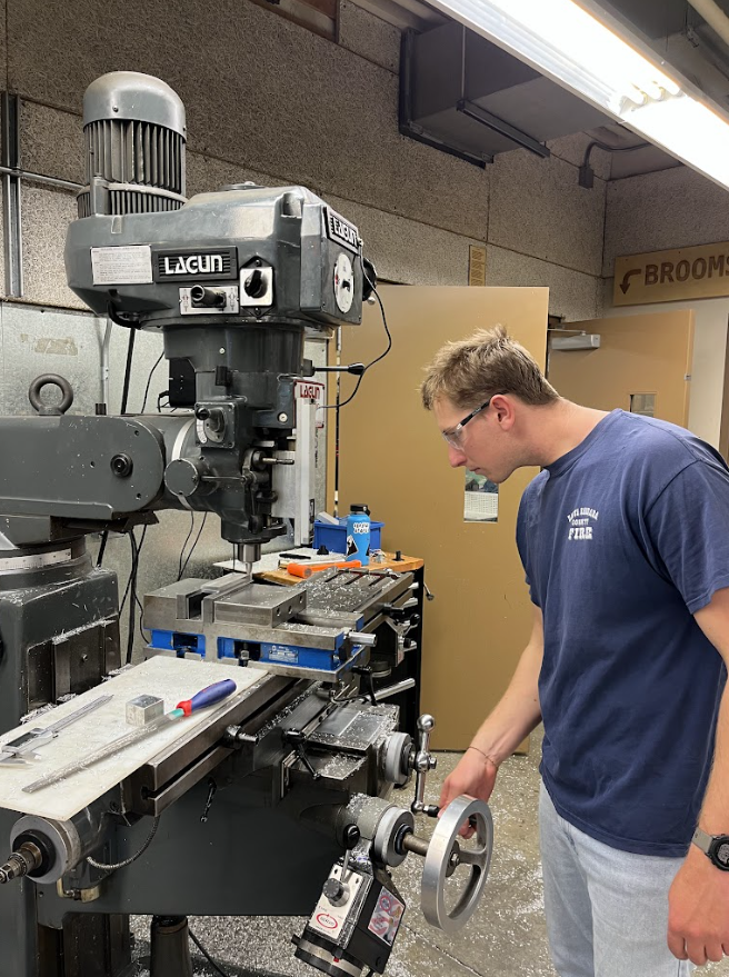
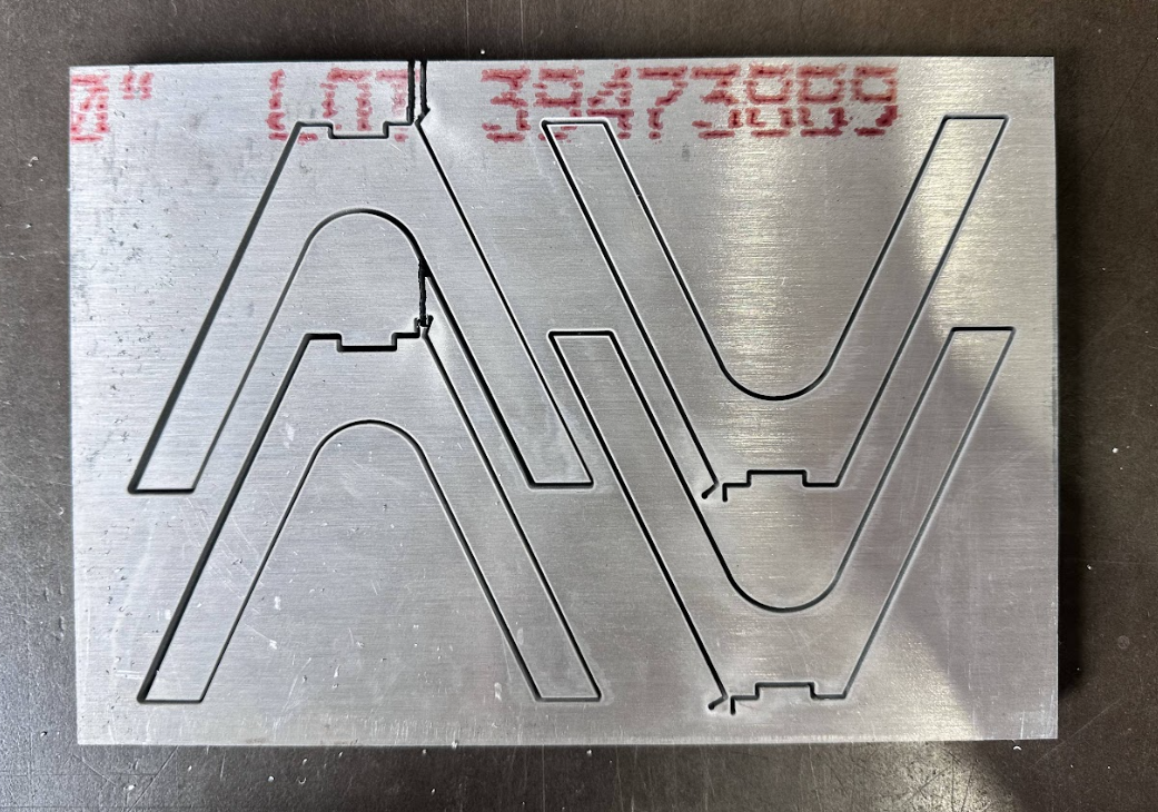
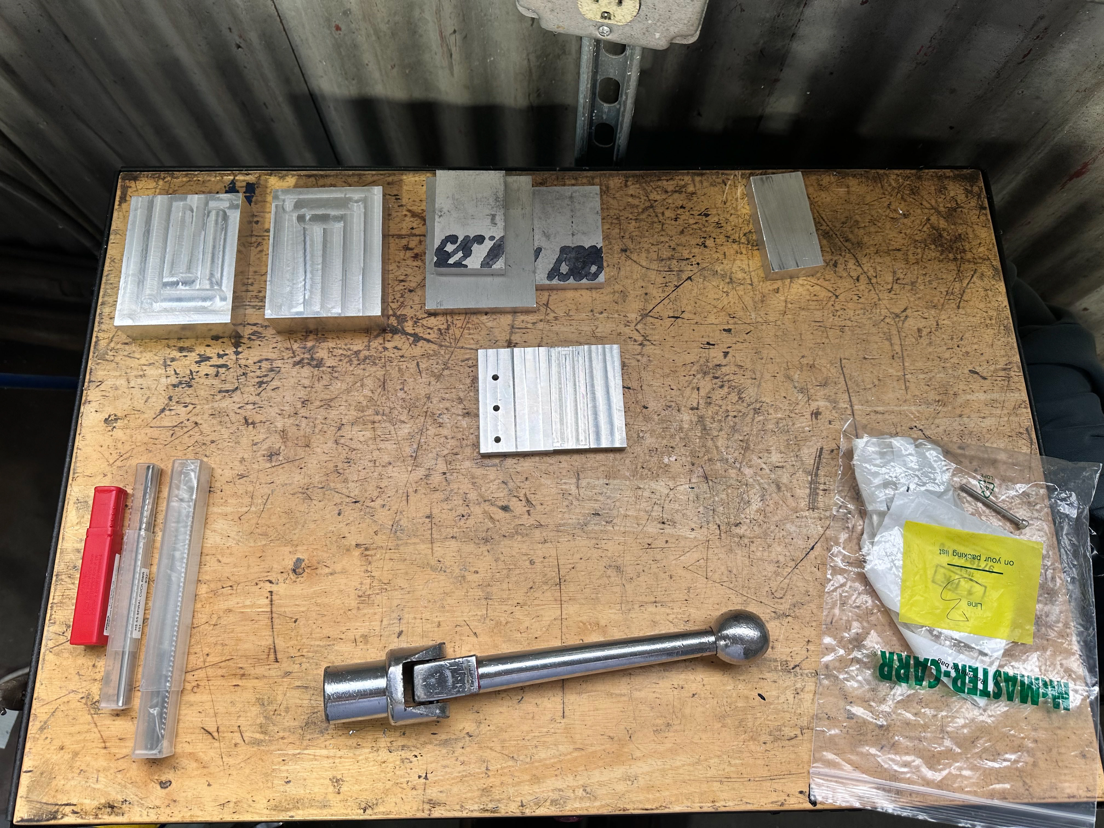
MACHINING:
Following validation through 3D-printed prototypes, we transitioned to machining the final components out of aluminum. Using CNC milling as our primary method, we developed a multi-step process for each part to ensure dimensional accuracy, manufacturability, and structural integrity.
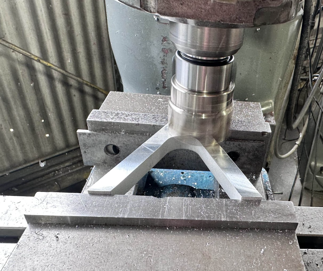
The saddle body required complex multi-face operations. We machined the top hole, interface slots, and mounting features across several orientations, finishing with precision reaming and slot milling. For the legs and fins, we used CNC profiling and pin-forming strategies, favoring repeatability and tight tolerances. The fins also included tab features for improved weld alignment.
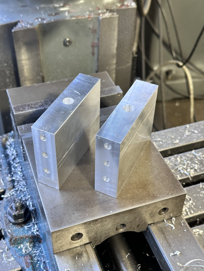
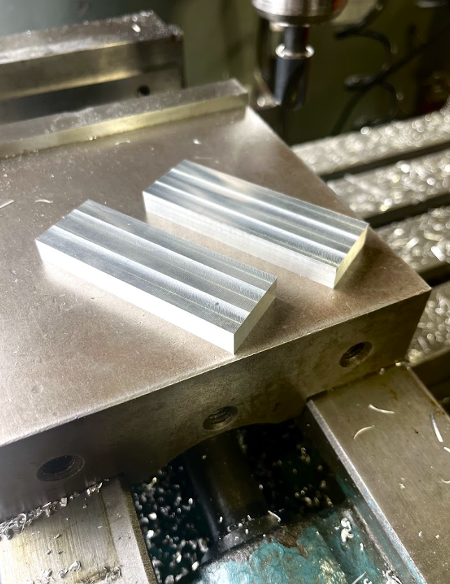
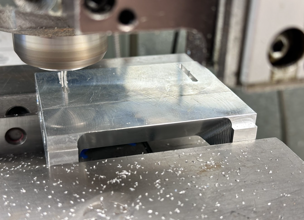
The cups were manufactured using a boring bar to achieve the curved inner profile, followed by additional CNC operations to add hose clamp slots and mounting holes. The spacers were produced manually on a mill and grinder, allowing finer control over face finishes and chamfers where needed.
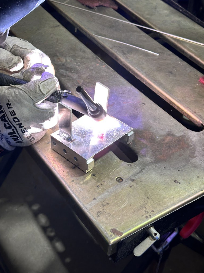
This phase emphasized fixturing, precision setups, and process sequencing—skills critical for complex, multi-part assemblies. Final parts were TIG welded, pressed with inserts, and assembled to specification, culminating in a robust, production-ready prototype.
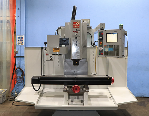
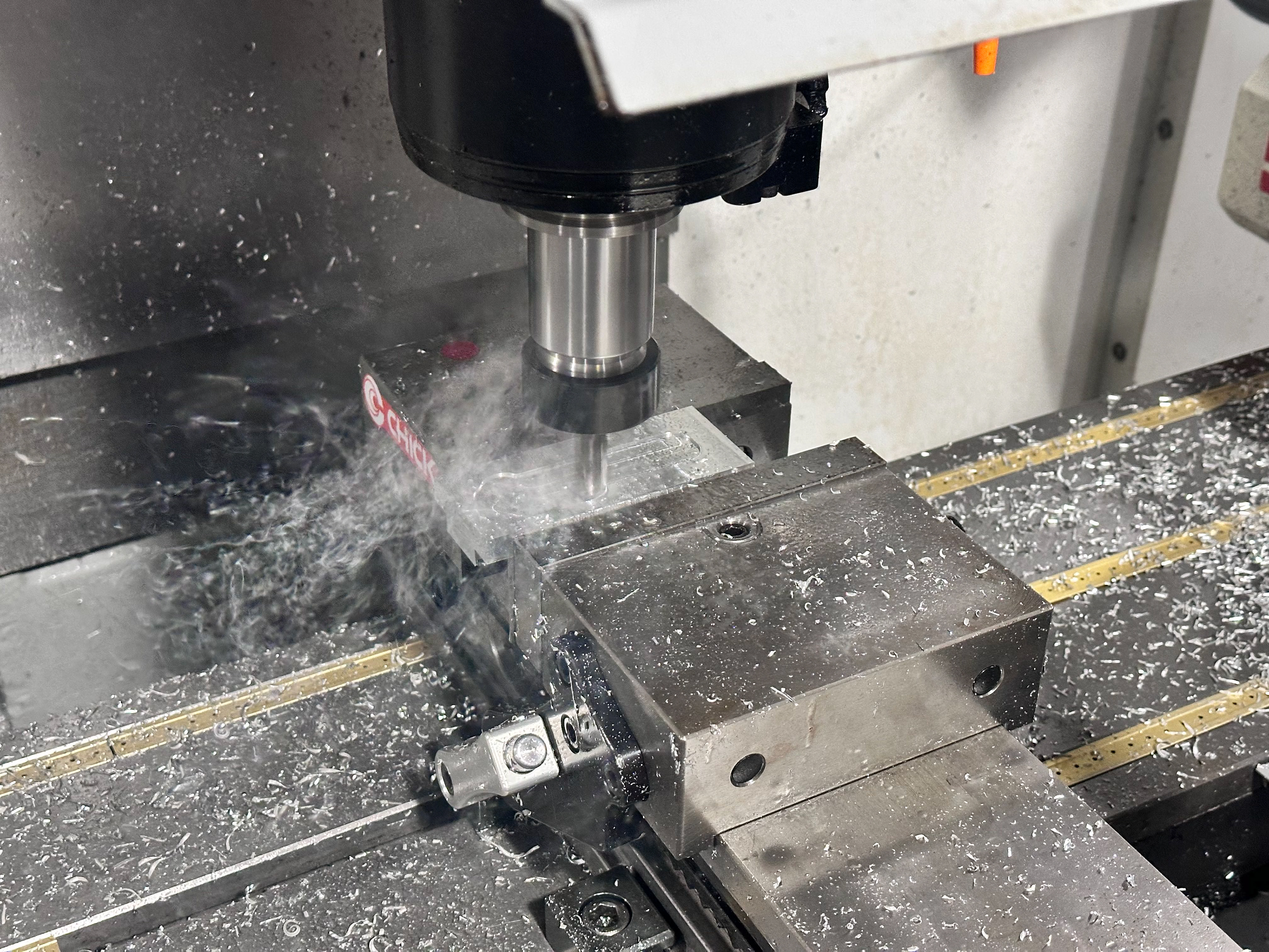
Below: Timelapse video of HAAS TM-2 CNC 3-Axis machine creating our "cups" parts
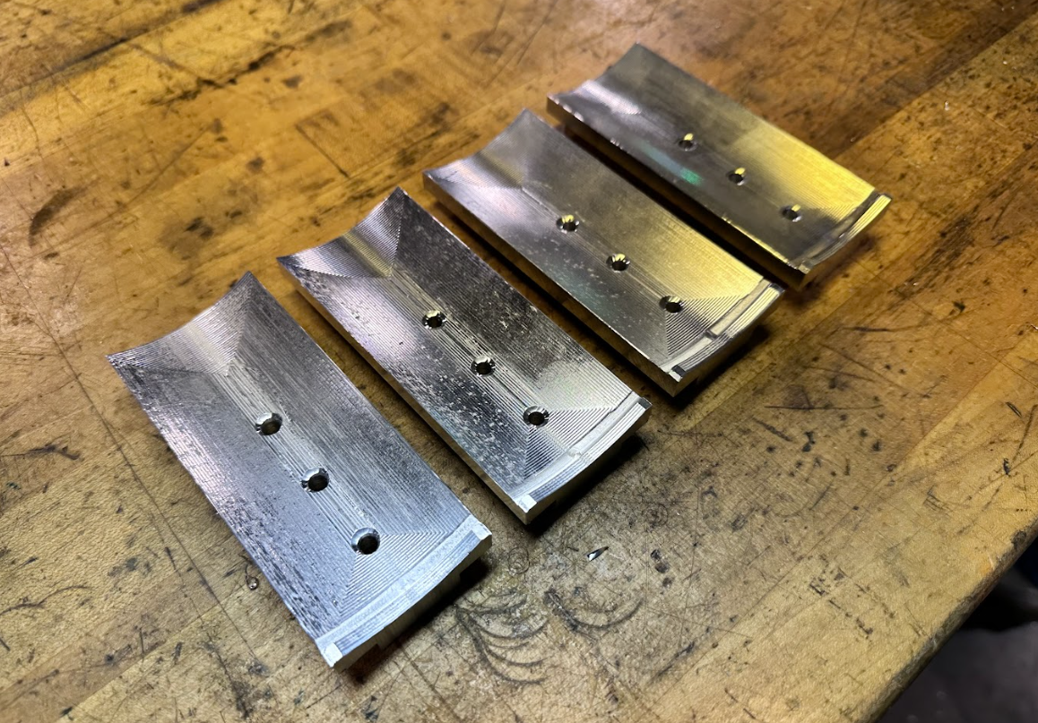
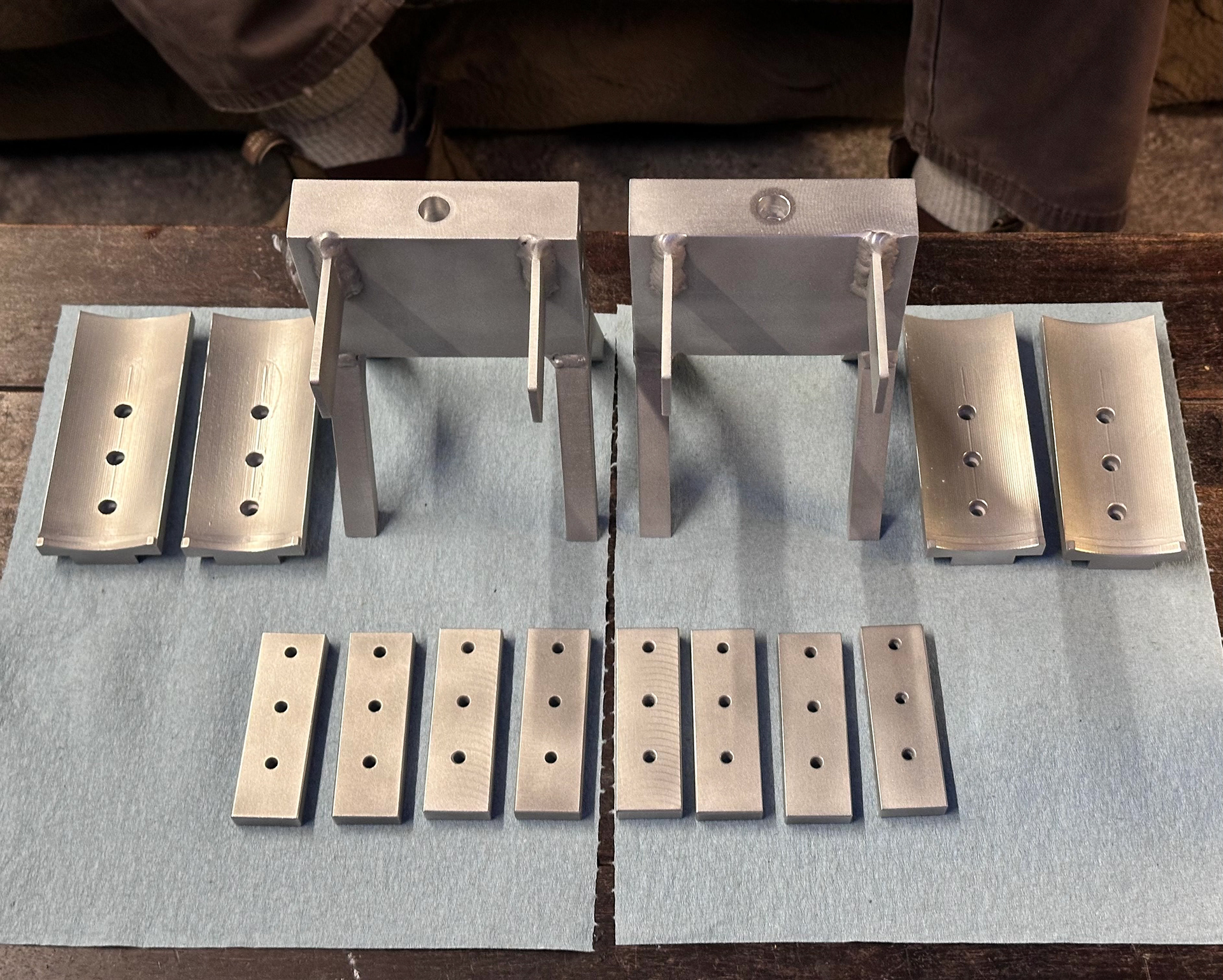
Right:
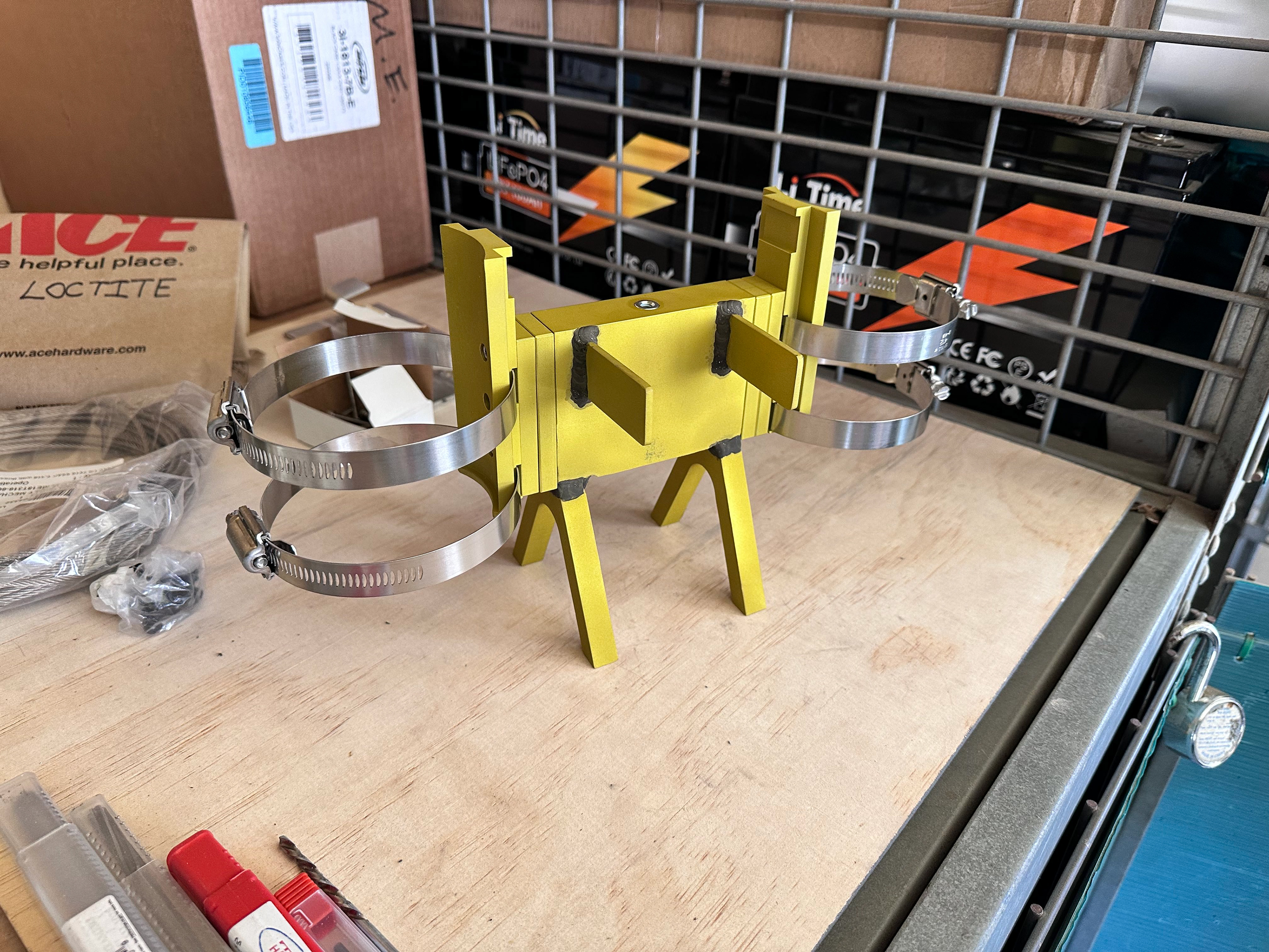
Fully machined, sandblasted, welded, and polished parts prior to sending out to Anodization
Below: Parts back from anodization!
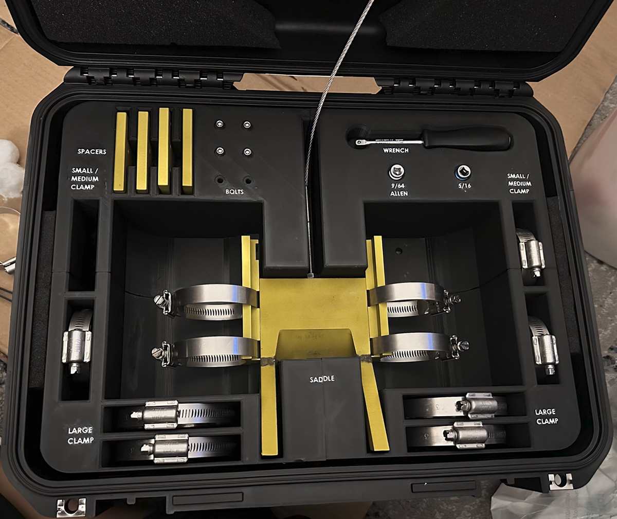
Below: Our team also bought custom waterproof cases, and used SolidWorks to CAD and 3D print a precise insert to hold all the parts and components.
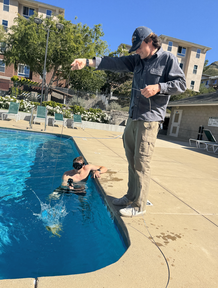
Below: After asembling our components, our team tested our design in the Poly Canyon Village pool at Cal Poly. Below are images from our Manueverability Test and our Captured Water test.

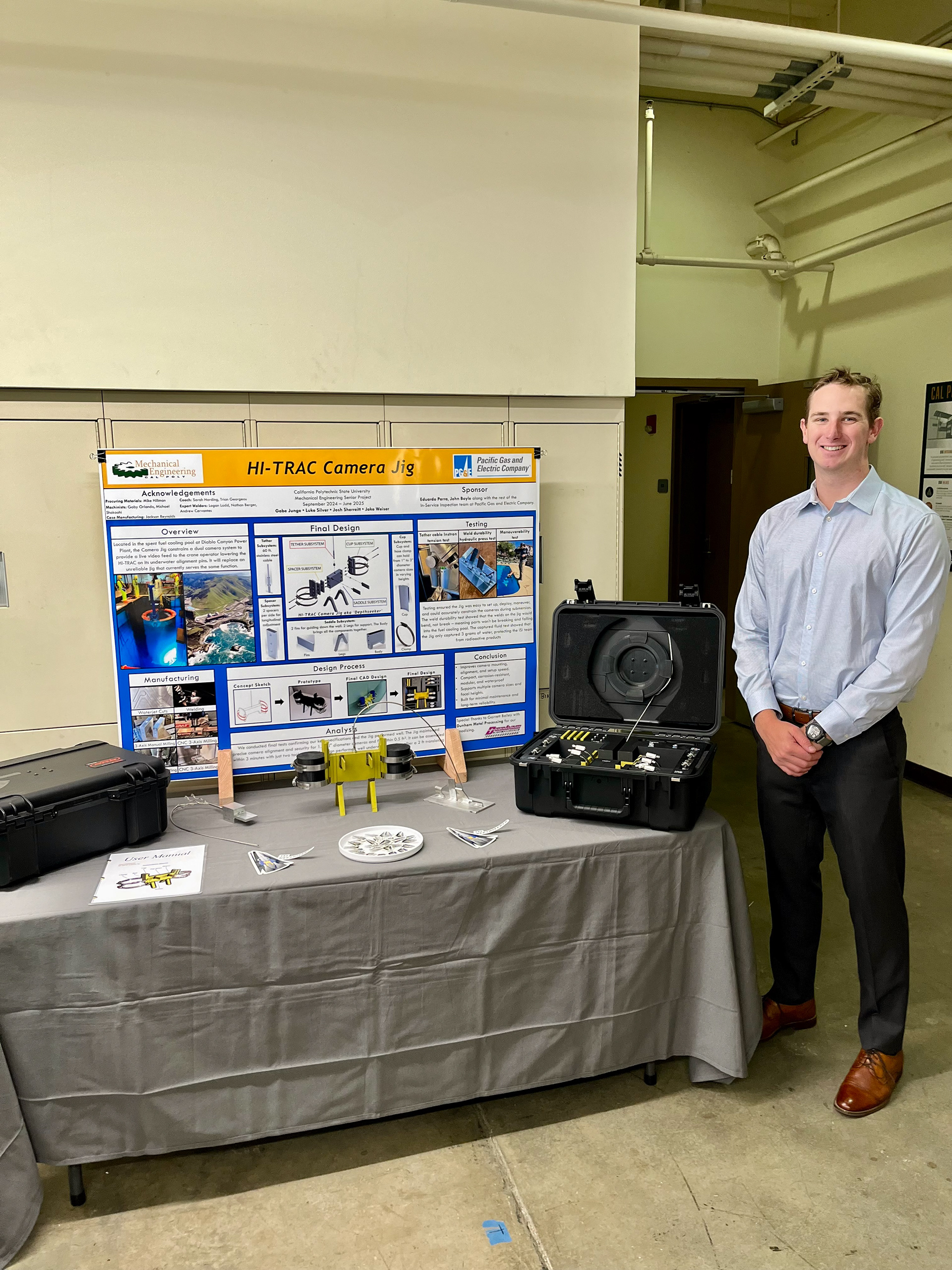
Following all of this, our team presented live at the 2025 California Polytechnic State University Engineering Expo on Friday, May 30th.
What I learned most from this project:
Through working on the HI-TRAC Camera Jig, I grew most in my ability to navigate trade-offs under real-world constraints. Designing for underwater alignment and nuclear safety wasn’t just a CAD exercise, it forced me to constantly reconcile manufacturability, precision, corrosion resistance, and ease of deployment. Every choice (material, fastening method, part geometry) had ripple effects on cost, durability, and usability.
I also learned the hard lesson that prototypes are not just about “making it look right.” They are diagnostics tools. The 3D printed iterations revealed critical fit/tolerance issues that would’ve torpedoed performance if left unnoticed. That early feedback was indispensable.
Finally, I sharpened my skills in cross-disciplinary communication: working with vendors, welders, machinists, and non-technical stakeholders (like PG&E). I learned how to translate technical implications (like choice of threads, weld strength, tolerances) into decisions others understood and acted on.